
Abstract
We succeeded in fabricating a CoFeB/MgO-based magnetic tunnel junction (MTJ) directly on an organic flexible substrate. The MTJ shows good strain endurance while keeping the tunnel magnetoresistance (TMR) ratio of ∼100% under various strained conditions; the TMR ratio is almost unchanged up to a tensile strain of 1.2%. Because of the magnetoelastic effect, the magnetic anisotropy fields for the top and bottom CoFeB layers are linearly proportional to strain with almost the same rate as that in a single CoFeB film, suggesting that the expected strain is added on both CoFeB layers in the MTJ pillar from the stretched flexible substrate.
Export citation and abstract BibTeX RIS

Content from this work may be used under the terms of the Creative Commons Attribution 4.0 license. Any further distribution of this work must maintain attribution to the author(s) and the title of the work, journal citation and DOI.
Flexible spintronics is a new area of electronics that can endow mechanical functions to spintronics devices.1–7) Spintronics itself, however, has been developed virtually without paying attention to stretchability of devices. For example, magnetic tunnel junctions (MTJs)8–12) formed on rigid semiconducting substrate is one of representative device, which have been widely used as a memory element in solid-state magnetic random access memory (MRAM) and as a read head in a hard disk drive (HDD). An MTJ generally consists of two ferromagnetic layers separated by a tunnel barrier. Large tunnel magnetoresistance (TMR) ratio (>100%) originated from the coherent tunneling of electrons through the crystalline MgO(001) barrier13) has been reported in epitaxial Fe/MgO-based or sputter-deposited CoFe(B)/MgO-based MTJs.10–12,14) The latter MTJs have currently been used in commercially available MRAM or HDD read head. However, a lattice-matched single crystalline substrate with the layers consisting MTJ is needed for the epitaxial layer growth in the former MTJs,10,14) and meanwhile, high temperature (>∼300 °C) post annealing process is required to crystalize MgO barrier to acquire large TMR ratio in the latter sputter-deposited MTJs.11,12) Because of these restrictions, the MgO barrier MTJ formed on an organic flexible substrate has been realized so far only using a transfer printing process.5) According to this report, to avoid a damage to flexible substrate by annealing, the MTJ array is first fabricated on a rigid thermally oxidized Si substrate and released bodily with SiO2 base by etching away the underlying Si, then, they are transferred and placed on the flexible substrate. MTJs fabricated on a flexible Si membrane has also been reported6) but an organic flexible sheet is needed in most cases to support the fragile Si membrane with the MTJs on it. In this paper, we fabricate a CoFeB/MgO-based MTJ directly on an organic flexible substrate without resorting to a transfer-and-print method. After high temperature post annealing process at 350 °C, the MTJ shows the TMR ratio of ∼100%. The properties and strain endurance of the MTJ are shown and discussed.
The layer structure deposited from the substrate side is as follows: Ta(1.7)/Ru(3.1)/Ta(1.9)/Co20Fe60B20(2.7)/MgO(3.3)/Co20Fe60B20(4.3)/Ta(2.2)/Ru(1.8) (numbers in parentheses indicate the thickness of each layer in nanometers). Ar gas was used for the sputter deposition. We employed a flexible polyimide substrate that has an excellent surface flatness (the root mean square ∼2 nm) and high glass transition temperature.
The MTJ device prepared here is illustrated in Fig. 1(a). Using photolithography and Ar ion milling, the layers consisting the MTJ with the Ta/Ru cap was defined into elliptically-shaped micro-pillar as displayed by a photo taken using a microscope in Fig. 1(a). Here the short axis of the ellipse is defined as x axis. The Ta/Ru/Ta layers underneath the MTJ part was remained for serving as a bottom electrode. After covering the whole area including the pillar by an insulator layer for an electrical isolation (30 nm thick Al2O3 formed using an atomic layer deposition technique at 100 °C), the Al2O3 part only on top of the pillar was lifted off. Subsequently, a top electrode composed of Cu(30)/Au(4.2) layers was formed by evaporation and lift-off process. Finally, the whole sample was annealed at 350 °C in an annealing furnace without applying an external magnetic field.

Fig. 1. (Color online) (a) The schematic illustration of the MTJ formed on a flexible substrate and measurement configuration. The Al2O3 isolation part is omitted from the illustration for simplicity. The inset shows a top view of the MTJ pillar before lift-off process taken by a microscope. (b) The MR curves measured under various ε. Hx is applied parallel to the stretched direction. (c) The TMR ratio as a function of ε. The inset shows the ε dependence of RP. (d) The inner and outer μ0Hc of the MR curves as a function of ε.
Download figure:
Standard image High-resolution imageAll results shown in this paper were obtained at room temperature. A four-terminal method was used to measure the resistance R of the MTJ. A four-terminal bias voltage V is positive when a current I flowing from the top to bottom CoFeB layer. To check the strain endurance of the present MTJ, the substrate with the MTJ on it was stretched along x axis using a miniaturized screw-driven tensile machine,15,16) while monitoring R under in-plane external magnetic fields along x and y axis. The nominal value of the tensile strain ε applied to the substrate, which was calibrated by observing the stretch of a reference structure on the substrate using microscope, can be tuned by a rotation number of the screw of the tensile machine. We note that ε shown below may include the deviation of at most ±0.2%.
Figure 1(b) shows the magnetoresistance (MR) curves obtained for various ε at V = +10 mV when the magnetic field along x axis (Hx) is swept. The vertical axis is (R − RP)/RP, where RP is R when the magnetizations of two CoFeB layers align in parallel (P) configuration. In spite of the high temperature post annealing process, clear TMR effect with the TMR ratio of ∼100% is observed in all MR curves, showing that the MTJ is successfully fabricated on the flexible polyimide substrate thanks to its high temperature endurance. Here the TMR ratio is defined as (RAP − RP)/RP, where RAP is the R when an antiparallel (AP) magnetization configuration is realized. Importantly, the TMR ratio is almost unchanged up to ε = 1.2%, and returns to the original value after the round-trip ε application as shown in Fig. 1(c). RP also shows reversible change but decreases with ε as shown in the inset, most likely due to the increase in the tunneling probability of electrons by the tensile-stress-originated reduction of the MgO barrier thickness. In addition, the coercivity Hc increases with ε as a result of the magnetoelastic effect. Figure 1(d) shows the inner and outer value of μ0Hc as a function of ε determined from each MR curve. Hc almost linearly and reversibly increases and decreases. Although how much the MTJ is strained will be discussed later, the results shown above clearly indicate that the tensile strain is actually applied to the MTJ as well as the present flexible MTJ is robust against the external stress. Note that the magnetic easy axis is along the short axis (x axis) of the elliptically-shaped MTJ pillar even at ε = 0%, probably because a tiny tensile strain is introduced to the substrate when it is gripped to the tensile machine.
Next, we discuss the bias dependences for the present MTJ. Figure 2(a) shows the I–V characteristics for the P and AP configurations. The I–V curve for the AP configuration is non-linear, whereas that for the P configuration is virtually linear, which is one of features for the MTJs with the (001)-oriented MgO barrier.17) The TMR ratio as a function of V is shown in Fig. 2(b). The TMR ratio drops to half at ∼0.6 V, which is also comparable with that of previously reported MgO barrier MTJs.10,17) Interestingly, the curves for ε = 0 and 1.2% is almost coincident, suggesting that the change in the tunneling electronic states is small within the range of ε employed in this experiment. Detailed tunneling spectroscopy may reveal the strain-induced modification of the tunneling electronic states.

Fig. 2. (Color online) (a) The I–V characteristics of the flexible MTJ for the P and AP magnetization configurations at ε = 0%. (b) V dependence of the TMR ratio for ε = 0% (solid) and 1.2% (dashed).
Download figure:
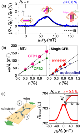
Standard image High-resolution imageFinally, we discuss the strain transfer from the stretched substrate to the MTJ structure. To examine this, the strain-modulated anisotropy field Hk for the CoFeB layers confined in the MTJ pillar and that in a single CoFeB layer deposited on the same flexible substrate are compared. First, Hk of the CoFeB layers in the MTJ was determined by applying the external magnetic field along y axis (Hy). Figure 3(a) shows a typical MR curve (in this case, ε = 0.6%) when Hy is swept down from positive high field. The magnetizations of both CoFeB layers align in the +y direction at high field, thus the MTJ is in the low resistance state [(R − RP)/RP ∼ 0]. By reducing Hy, the resistance increases because the magnetization of one CoFeB layer with larger magnetic anisotropy (CFB1) starts to rotate toward x direction due to the uniaxial anisotropy created by the tensile strain along the x axis. At μ0Hy = 0 T, the magnetizations of CFB1 and the another layer (CFB2) align in the parallel configuration along the x axis because of the strain-induced uniaxial anisotropy, thus, the MTJ again becomes low resistance state. As shown in Fig. 3(a), the MR curve can be fitted well by the simulated curve, where the coherent magnetization rotation model is utilized to calculate the magnetization rotations for CFB1 and CFB2 as Hks for the both layers are the fitting parameters (for the details, see Ref. 7). μ0Hk as a function of ε determined as above is plotted in the left panel of Fig. 3(b). The slope of the linear fitting to the data for CFB1(CFB2) is 135(91) mT per ε = 1%. Thus, if the strain is perfectly transferred from the substrate to the MTJ, the effective magnetoelastic coupling constant Bxy (≡μ0HkM/2ε, where M is the saturation magnetization of CoFeB measured using a superconducting quantum interference magnetometer) for CFB1(CFB2) is 8.9(6.0) MJ m−3.
Fig. 3. (Color online) (a) The MR curve of the MTJ for ε = 0.6%. Hy is applied normal to the stretched direction and swept down from the high field. The dashed line indicates the fitted curve using the simulation. The schematics show the magnetization configurations for CFB1 and CFB2 at each Hy with the indications of strain and Hy. (b) The ε dependence of μ0Hk for CFB1 and CFB2 in the MTJ (left panel) and for the as-deposited and annealed sample with the single CoFeB layer (right panel). The dashed lines indicate the linear fitting to the data. (c) The AMR curve for the annealed single CoFeB sample at ε = 0.3% (main panel) with the schematic illustration of the wire structure and measurement configuration. The inset in the panel shows the hard-axis magnetization curve ( as a function of μ0Hy) reproduced from the AMR curve.
Download figure:
Standard image High-resolution image
On the other hand, Hk for the single CoFeB sample [Ta(1.7)/Ru(3.1)/Ta(1.9)/Co20Fe60B20(4.3)/MgO(3.3)], which was additionally deposited for this purpose, was determined using the anisotropic magnetoresistance (AMR) effect. To measure this effect, the layers were fabricated into a 30 μm wide wire with probes for a four-terminal resistance R4wire measurement as schematically illustrated in the left side of Fig. 3(c). As-deposited and 350 °C-annealed samples were prepared for the measurement. The wire direction is along the x axis, and the tensile strain was applied along it. A typical AMR curve for the annealed sample (in this case, ε = 0.3%) is shown in the main panel of Fig. 3(c). R4wire decreases and saturates with increasing the magnitude of Hy, because the magnetization of the CoFeB layer rotates from the x (easy) to y (hard) direction. From the AMR curve, the normalized hard-axis magnetization  curve can be calculated16) as shown in the inset. The shaded area corresponds to Hk/2 (=
  ), from which μ0Hk for various ε shown in the right panel of Fig. 3(b) is obtained. The slope of the linear fitting to the data for the annealed (as-deposited) sample is 127(93) mT per ε = 1%, thus, Bxy for the perfectly-strain-transferred condition is determined to be 8.4(5.5) MJ m−3, which is in agreement with Bxy for the MTJ structure. The results suggest that the strain is transferred from the substrate to the CoFeB layers in the MTJ at least with the same level as the case of the single-layered sample without any isolation layer or additional electrodes. Since Bxy for the annealed single CoFeB sample is larger than that for the as-deposited sample,18) the variation of the degree of annealing-promoted crystallization may be one possibility for the difference in Bxy between CFB1 and CFB2 in the MTJ.
In summary, we have successfully fabricated the CoFeB/MgO-based MTJ on the organic flexible substrate. A much larger TMR ratio (∼100%) has been obtained in our MTJ compared to the previously reported Al2O3 barrier MTJs formed directly on flexible substrates.19,20) Although a flexible spin–orbit device has already been reported,3) a spin-transfer-torque (STT)-induced magnetization switching21–23) in our MTJ clearly becomes our future task to realize a flexible STT-MRAM. Our flexible MgO barrier MTJ can be fabricated as in the case of conventional MTJs on rigid Si substrates and is robust against unwanted heating and stress. These facts are highly desirable for future high-sensitive flexible spintronic sensors,1,2,4,7) and non-volatile memories that can be equipped around various flexible devices.
Acknowledgments
The authors thank Y. Hibino, T. Hirai, S. Kasai, T. Nagahama, T. Namazu, H. Murayama, Y. Iwasa, Y. Nakagawa, S. Ono, and M. Kawasaki for useful discussions and technical help. This work was partly supported by the JSPS KAKENHI (Grant No. JP17J03125), Murata Manufacturing Co., Ltd. and Spintronics Research Network of Japan. A part of the work was performed using facilities of the Cryogenic Research Center, the University of Tokyo.