
Abstract
The accuracy of many biological and chemical sensors is critically dependent on the stability of the potential imposed or sensed through a reference electrode. As these sensors are miniaturized, the reference electrode has to be miniaturized simultaneously without any loss to its stability. In this paper, we describe a new microfluidic miniaturized silver/silver chloride reference electrode that demonstrates significantly better stability and lifetime than conventional designs. In our new design, we have miniaturized the existing format of the macroscale reference electrode and added the capability to replenish the internal solution by integrating it with a microfluidic channel. The replenishment of the internal solution significantly improves the performance of these electrodes over other miniaturized designs. We demonstrate reference electrodes that are very stable (potential variation of <0.1 mV), with minimal drift (∼1 mV) and lifetimes longer than 100 hours. We have also characterized the behavior of these electrodes to changes in pH and chlorine concentration of the external solution. The results indicate insensitivity of the microfluidic reference electrode potential to the presence of any analyte in the test solution.
Export citation and abstract BibTeX RIS
Biosensors for medical diagnostics increasingly use genomic information (DNA) to rapidly and accurately identify pathogenic species that may be present in the fluid sample. Since DNA inherently has a negative charge, electrical measurement of the charge provide a direct method to sense DNA. Such a sensing is feasible using a biological field-effect-transistor (BioFET) structure. In a BioFET, hybridization of a single stranded DNA (indicative of the biological species) from the sample solution with a complementary strand immobilized on its gate dielectric causes a change in the transistor characteristics that could be read out as an electrical signal.1–5 For instance, changes in threshold voltage of ∼11 mV have been observed upon hybridization at very high concentrations of DNA.6 In such systems, imposition of a highly stable potential through a miniaturized reference electrode on the gate becomes imperative to obtain highly accurate sensing.
Reference electrodes have been studied extensively in past due to their wide applications in areas such as corrosion, electroplating, electroencephalography, and analytical measurements,7–9 where a potential is to be imposed or sensed in a solution. They can be categorized based on their chemistries into different kinds, such as the standard hydrogen (Pt/H2), calomel (Hg/Hg2Cl2), and silver/silver chloride (Ag/AgCl) electrode. While all of them provide a stable potential due to high exchange current density at the interface, the Ag/AgCl reference electrode is the one that is easiest to miniaturize.10
Microfabrication techniques, utilized so far to miniaturize the Ag/AgCl electrode, can be mainly categorized into two groups - screen printing11,12 and conventional photolithography13–15 methods. As an example, Tymecki et al.11 reported a drift of <25 mV over 100 hours and lifetime of 1 week employing a screen-printed Ag/AgCl electrode. Alternatively, by using a photolithographic technique to manufacture the electrode, Suzuki et al.16 reported better stability of <1 mV, but with a shorter life time of about 100 hours.
Although many attempts have been made to improve the performance of microfabricated Ag/AgCl reference electrodes, the current microfabricated ones generally have short lifetime10 and higher fluctuations in potential as compared to their macroscale counterparts. Those with longer lifetime typically have higher drift13 and/or needs complex microfabrication processes.16 These can be attributed to the configurations of Ag/AgCl electrode which have been used so far, such as quasi-solid-state,17 solid-state13 and liquid junction16–18 formats. In these configurations, parameters such as the surface properties of Ag/AgCl electrode, filling solution, and the changes in composition of the liquid junction over time have a direct effect on the electrode's performance. One configuration that has been explored by Simon et al.19,20 in the macroscale, but has not been widely implemented due to its complex manufacturing, is the use of free-diffusion liquid junction. In this configuration, the filling solution is replenished continuously by a flow of the internal solution through the reference electrode liquid junction producing a highly stable potential as it maintains the composition of the liquid junction over time.
When an Ag/AgCl electrode is in contact with an analyte solution, reaction (1) is established at the interface:
![Equation ([1])](https://content.cld.iop.org/journals/1945-7111/160/10/B177/revision1/jes_160_10_B177eqn1.jpg)
The equilibrium potential of this reaction is given by the Nernst equation:21
![Equation ([2])](https://content.cld.iop.org/journals/1945-7111/160/10/B177/revision1/jes_160_10_B177eqn2.jpg)
where E is the equilibrium potential, E0 is the standard reduction potential of the electrode against the standard hydrogen electrode, R is the universal gas constant, T is the temperature in Kelvin, F is Faraday's constant, and Canalyte is the concentration of chlorine in the analyte solution. In this case, the solubility of the AgCl in the analyte solution leads to dissolution and changes at the Ag/AgCl interface.16 Accumulation of Cl− ions in the vicinity of the electrode due to dissolution leads to deviation from standard potential (see equation 2) – this is referred to as drift in the potential. Such electrochemical process continues until AgCl is completely consumed. At this point, the potential suddenly drops indicating the end of the electrode's lifetime.
One important parameter in selecting a reference electrode is its stability. Here, stability is defined as a measure of the ability of the electrode to maintain a constant potential during the analysis period (in our case ∼ 1hr) and for several consecutive analysis. The stability of the potential is dependent on exchange current density of the electrochemical reaction at the electrode/electrolyte interface. A higher exchange current density results in a lower change in the electrode's overpotential to any flow of current through the interface, which leads to a more stable potential. The exchange current density itself is a function of some intrinsic properties of the electrode and the concentration of surrounding reactants (here Cl−).21 For Ag/AgCl electrode, the exchange current density is about 1 A/cm2.22
The lifetime of the electrode can be increased by placing the Ag/AgCl electrode in a standard KCl solution that is then separated from the analyte through a membrane with a liquid junction. When the reference electrode has a liquid junction which separates the standardized inner solution from the external solution, the equilibrium potential (E)23 of the electrode is modified from equation 2 to:
![Equation ([3])](https://content.cld.iop.org/journals/1945-7111/160/10/B177/revision1/jes_160_10_B177eqn3.jpg)
where σ is the fixed ions on the pores' inner wall of the junction, Cinternal is the concentration of the internal solution and Cexternal is the external chlorine concentration. In this format with the liquid junction, parameters such as surface properties of Ag/AgCl electrode, filling solution, and liquid junction have a direct influence on reference electrode's performance. For instance, electrode properties such as high effective surface area are crucial for the stability of the potential of the reference electrode. Miniaturization reduces the effective surface area and consequently decreases stability of the reference electrode. In addition, changes in the concentration of Cl− ions in the inner solution have a direct effect on the potential of the electrode (equation 3). Finally, the potential drop across the liquid junction could change due to changing composition across the liquid junction because of convection, electrophoresis, and diffusion (equation 3) which could be caused by differences in pressure, electric potential and concentration across the liquid junction.
Maintaining the concentration of Cl− in the inner solution constant and its composition across the liquid junction is difficult in the microscale format especially in the solid-state configuration. One ingenious method that has been employed for macroscale electrodes was to introduce a steady convective flow through the junction. This is known as free-diffusion liquid junction and it minimizes the electrophoretic and diffusional effects and generates a stable and static junction potential.19,20,23 Free-diffusion configuration introduces the following static potential to the overall reference electrode's potential which can be easily calculated:
![Equation ([4])](https://content.cld.iop.org/journals/1945-7111/160/10/B177/revision1/jes_160_10_B177eqn4.jpg)
where ΔU is the potential drop within the junction, Cjunction is concentration of ion of interest (here chlorine) inside the junction, and Cexternal in external solution, respectively. If the convective flow rate within the junction is kept sufficiently high to balance the effect of diffusion, the Cjunction will quickly be equal to internal chlorine concentration and be stable over the duration of use of the reference electrode. Since concentrated internal solution is used,  will be smaller and results in static potential drop across the junction.23 Using this format, the liquid junction potential can be minimized and made more stable; that is, the electrode can provide a rapid response, and will be insensitive to dilute external solution.
In this paper, a microfluidic Ag/AgCl reference electrode with free-diffusion liquid junction is fabricated and tested for the first time. It is operated in several modes and characterized in test solutions with various pH and chlorine concentrations. Simultaneously, a solid-state Ag/AgCl electrode is also tested to assess the effect of device configuration on the electrode's performance.
Experimental
Design
The microfluidic device design (Figure 1) mimics the macroscale reference electrode in its construction. It consists of a silver wire that has a thin layer of nanostructured silver chloride electrodeposited on it. This wire is embedded in a microchannel that contains the inner solution of the reference electrode. The microchannel has fluidic interconnections to convectively transport the inner solution. The central region of the microchannel is made nanoporous and serves as an interface with the external solution, similar to the porous plug in the conventional reference electrode.
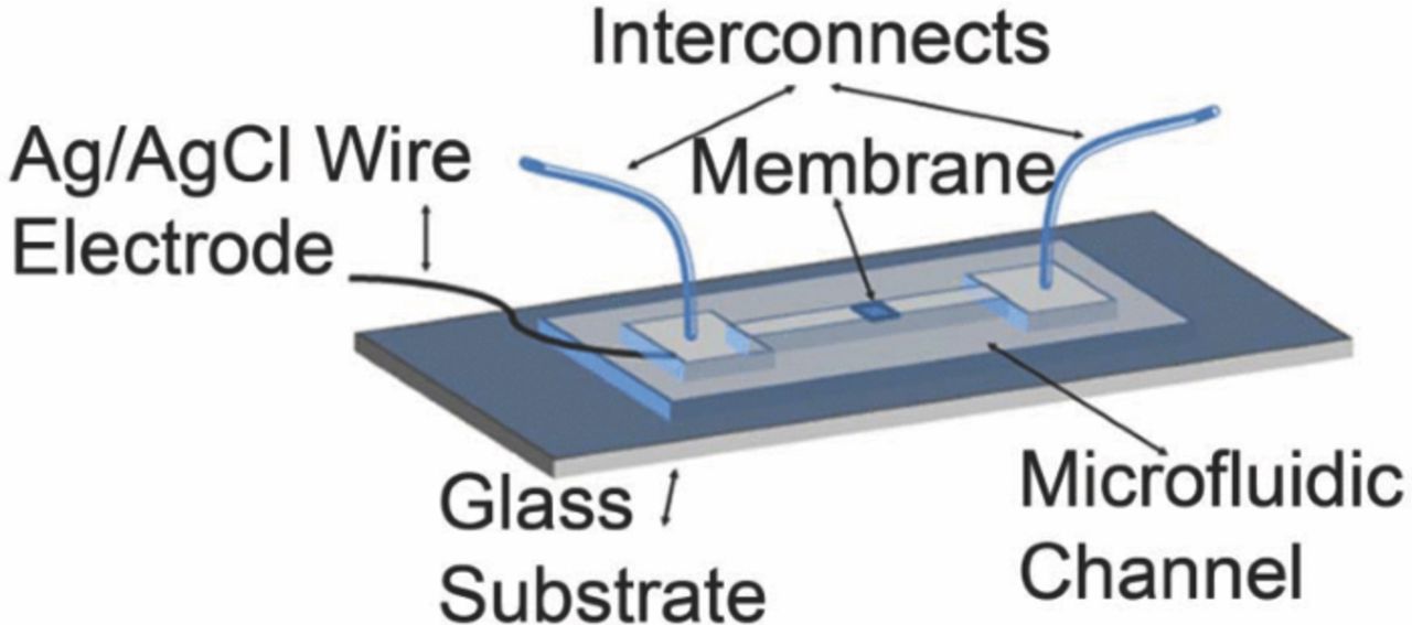
Figure 1. Schematic of the microfluidic reference electrode device. The nanoporous membrane separates inner electrolyte from the external solution. The microfluidic channel replenishes the inner solution which maintains liquid junction stable.
Materials and Apparatus
Silicon wafers (mechanical grade, 3'', 500 μm thick) were purchased from University Wafer Co., USA. Negative photoresist Su8-100 and developer were provided from Microchem Co., USA. PDMS polymer was purchased from Dow Corning Co., Canada. Nanoporous polycarbonate (PC) membrane and Ag wire (99.99% purity, 200 μm) were obtained from GE Osmonics Labstore and Harvard Apparatus Canada, respectively. Commercial Ag/AgCl reference electrode was purchased from Sigma Aldrich Co., Canada. The Agilent 4156C semiconductor parameter analyzer (SPA) was used for open-circuit potential measurement.
Fabrication
The fabrication of the microfluidic reference electrode is shown in Figure 2. First, SU-8 100 photoresist is spun on a Silicon wafer at 500 rpm speed for 30 sec, gradually ramped up to 1,700 rpm in 6 sec and then kept spinning for 40 sec to produce a film of 80 μm thickness. This layer was patterned using photolithography and produced features that constituted the mold to form the microchannel (Figure 2A). The PDMS pre-polymer (base: curing agent = 10:1) was cast on the SU-8 mold and cured at 80°C for 2 hours to form an elastomeric film (Figure 2B). The elastomer was peeled from the mold, replicating microchannels 500 μm wide × 3 cm long × 80 μm high with two reservoirs 5 mm × 5 mm at both ends (Figure 2C). The top surface of the microchannel was cleaned using oxygen plasma at 50 W for 1 min.
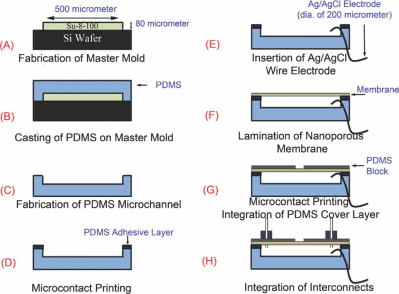
Figure 2. Process flow (A) master mold fabrication by soft-lithography technique (B) making PDMS microchannel by casting 10 base:1 agent PDMS on fabricated master mold (C) removing PDMS microchannel from master mold (D) deposition of PDMS adhesive layer on microchannel top surface by microcontact printing (E) attaching electrochemically prepared Ag/AgCl electrode to one reservoir of the microchannel (F) attaching 100 nm membrane to the microchannel (G) sandwiching the membrane between the microchannel and a PDMS top layer (H) fluidic interconnects attachment.
A thin adhesive PDMS pre-polymer layer was microcontact printed onto the top elevated surfaces of the PDMS microchannel in order to attach a thin nanoporous PC membrane (Figure 2D). In this microcontact printing process, PDMS pre-polymer (base: curing agent = 1:3) was spun on a clean Silicon wafer at 10,000 rpm for 4 min to obtain a ∼10 μm thick film. Then, the PDMS microchannel elastomer layer is brought into contact with the pre-polymer film briefly and removed. This process brings the elevated regions of the elastomer into contact with the pre-polymer layer and patterns (prints) the adhesive only in those regions.
After microcontact printing, a thin (200 μm diameter) Ag/AgCl wire, which serves as the electrode was inserted into one of the reservoirs (Figure 2E). The Ag/AgCl wire was prepared using a new process that has been developed in our laboratory which enhances the stability of the reference electrode's potential.24 In this process, the Ag wire (200 μm diameter) is cleaned by rinsing with acetone and diluted HCl (0.01 M) and rinsed with DI water. Subsequently, an asymmetric potential waveform (square wave) with anodic amplitude of 2 V, cathodic amplitude of −200 mV, and frequency of 0.5 Hz was applied for 15 min in 1 M KCl. The anodization process with this waveform led to formation of nanosheets of AgCl on the silver wire and highly stable potential23 (Figure 3). Once the wire was inserted without damaging the nanosheets, a polycarbonate nanoporous membrane (100 nm pore size, 6 μm thick) was laminated on the microcontact printed microchannel top surface (Figure 2F). This step sealed all the pores in the nanoporous membrane in all regions except at the microchannel.
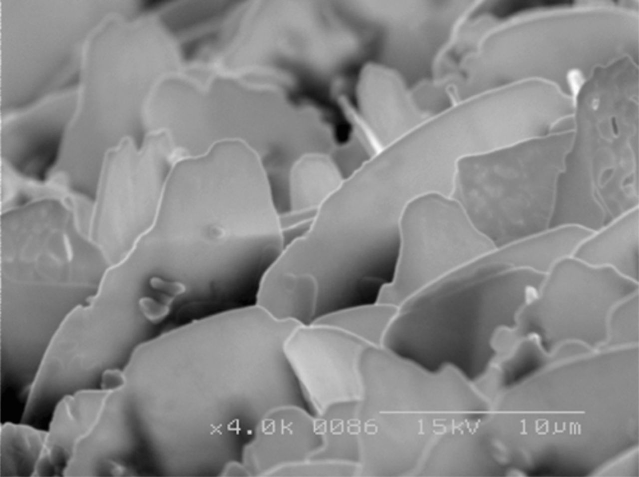
Figure 3. SEM images of anodically grown AgCl on Ag wire by applying DC potential of 3 V in 1 M KCl24 (reproduction with permission from IOPscience, IOPscience 2011).
The nanoporous membrane was then patterned on the other side with PDMS pre-polymer by microcontact printing with another PDMS stamp that blocked the pores in all other regions of the nanoporous PC membrane except a square opening 500 μm × 500 μm over the middle of the microchannel where the pores were open. The open area serves as the interface to the external solution for the reference electrode operation (Figure 4). Subsequently, a PDMS top layer (2 cm wide, 5 cm long, 1 mm thick) with a central opening for open area of the membrane and two through holes (1.2 mm in diameter) for interconnects was bonded onto the membrane using microcontact printing to support the membrane (Figure 2G). The device was cured at 80°C for 4 hours.
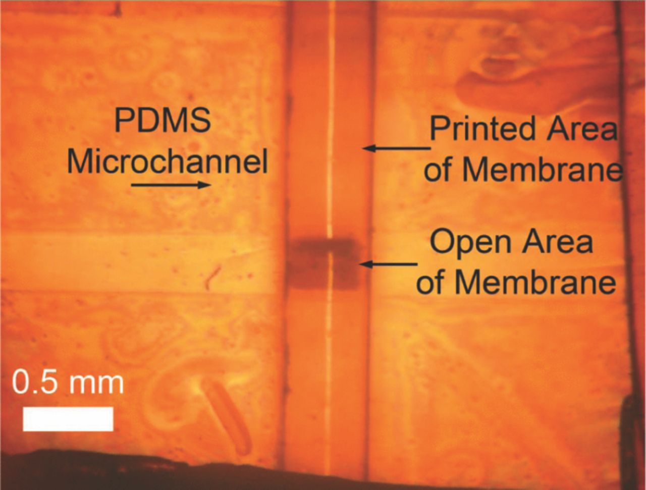
Figure 4. Microcontact printed polycarbonate membrane with opening of 0.5 mm by 0.5 mm which bridges internal and external solutions.
Fluidic interconnections were added by attaching two PDMS blocks (1 cm wide, 1 cm long, 5 mm thick) with Tygon tubes (1.2 mm diameter) in their center to the reservoirs by PDMS bonding (Figure 2H). The silver wire external to the microchannel was shielded by encasing it in a plastic tube with inner diameter of 1.6 mm filled with PDMS pre-polymer at the connection area and cured. Finally, the microchannel was filled with 3M KCl solution and the reference electrode was ready to use. The fabricated microfluidic reference electrode is shown in Figure 5.
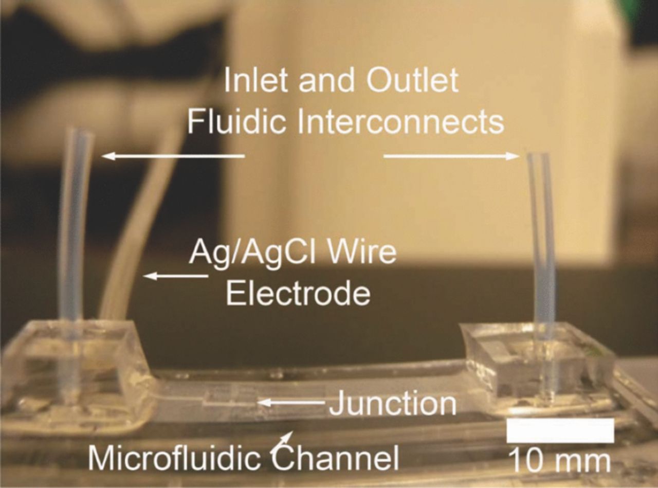
Figure 5. Picture of final device (3 cm long and 1 cm wide) after attaching the interconnects.
Experimental Setup
Open-circuit potential (OCP) measurement of the solid-state Ag/AgCl electrode was performed by immersing the AgCl region of the Ag/AgCl wire in phosphate buffer saline 10X (PBS) and measuring its OCP against the commercial Ag/AgCl reference electrode using an Agilent semiconductor parameter analyzer. Similarly, the microfluidic reference electrode (solid-state Ag/AgCl electrode embedded in the microchannel with KCl inner solution filled) was held in PBS solution using a laboratory clamp and tested in 3 modes of operations.
- The first mode as shown in Figure 6 is that of a stationary liquid junction which is typical in commercially available reference electrode and where the solid-state Ag/AgCl wire is immersed in an inner solution and interacts with the external solution through a membrane. There is no convective flow of solution in this configuration.
- The second mode as shown in Figure 7a illustrates the reference electrode in which internal solution is flowed inside the microchannel by means of a syringe pump.
- The third mode shown in Figure 7b is where the internal solution could be flowed, by means of a syringe pump, across the nanoporous membrane. This configuration is termed free-diffusion liquid junction. The internal solution was filtered with 450 nm pore size filter to eliminate particles and bubbles that could clog the membrane.
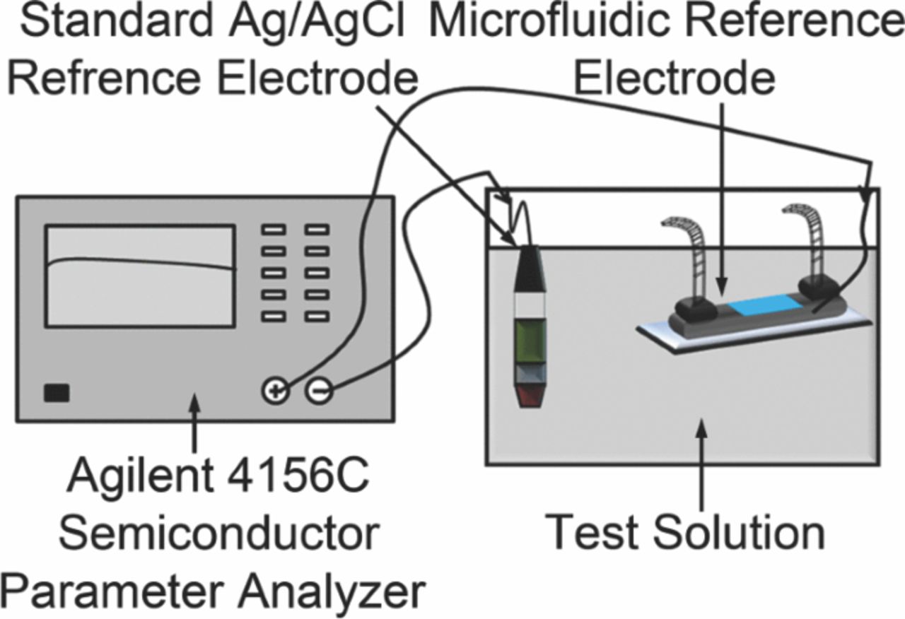
Figure 6. Schematic of stability test set-up of the stationary liquid junction microfluidic reference electrode.
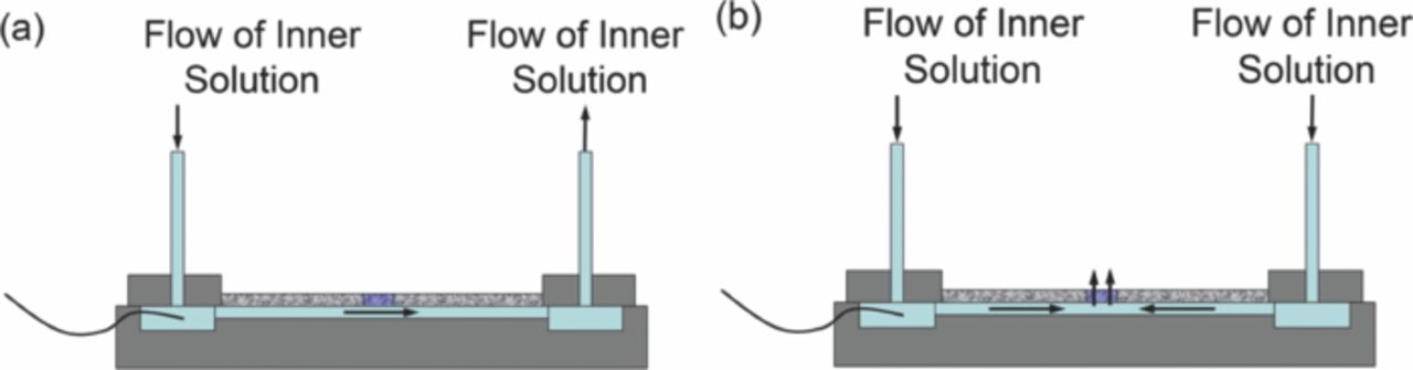
Figure 7. Schematic of stability test set-up of the liquid junction microfluidic reference electrode with (a) flow of the internal solution through the microchannel (b) free-diffusion liquid junction.
Depending on the microfluidic reference electrode configuration, some pre-treatments are essential to ensure that the pores of the hydrophobic PC membrane are filled with solution and do not have trapped air bubbles. In the case of the stationary liquid junction reference electrode (Figure 6) and a configuration with the flow of KCl through the microchannel (Figure 7a), the inlet and outlet were connected to a vacuum chamber to generate a suction pressure across the membrane. At the same time, several KCl droplets were left on the open area of the membrane to fill the pores. Then, the microchannel was disconnected from the vacuum chamber and filled with 1 M KCl and the external surface of the open region membrane was kept in contact with 1 M KCl.
An asymmetric potential (anodic and cathodic potential of 5 V, duty cycle of 50% and frequency of 1 Hz) was applied between the internal solution and the external KCl for 10 minutes. This procedure facilitates removal of trapped air in the pores and filling them with the internal solution (1 M KCl) that can shorten the initial stabilization time. In free-diffusion liquid junction case (Figure 7b), in addition to the aforementioned pre-treatment and in order to establish a steady state flow of the internal solution inside the pores, the internal solution with flow rate of 2 μL/ hr was flowed through the membrane for 5 hours before the actual experiment. It should be noted that this pre-treatment step can be eliminated if hydrophilic nanoporous membranes were used.
Long term open-circuit potential measurements of the microfluidic reference electrode (with the optimum pore size and flow rate) in different modes of operations were performed. Furthermore, effect of the pH of the external solution was tested by adding acetic acid to the external solution to decrease pH. Also, in order to investigate the effect of chlorine concentration of the external solution, the stationary liquid junction microfluidic reference electrode was tested in KCl solutions of various concentrations (10 mM – 3 M). An Agilent 4156C semiconductor parameter analyzer was used to collect the measured open-circuit potentials.
To calculate the stability of the electrode, the entire operation time was divided into 1 hour slots and the data in each 1-hr window was averaged. The electrode potential was considered to be stable unless the ratio of the change in the 1 hour average potential over the adjacent time interval varies by more than 1%. Variance of the potential within the 1 hr averaging window was computed and this variance was averaged over lifetime of the electrodes to obtain its potential hourly averaged fluctuations potential (stability). The difference between the maximum and minimum potential over the entire lifetime was considered as the drift in potential.
Results and Discussion
Instability and drift in microfluidic reference electrode and its comparison with solid-state reference electrode
The microfluidic reference electrode with 100 nm pore size membrane and open area of 500 μm × 500 μm was selected (see experimental section). It was tested against a commercial reference electrode, as explained in experimental setup. The OCP of the solid-state and the microfluidic reference electrode with the stationary junction is shown in Figure 8. They have different starting potential since the solid-state electrode is in a direct contact with PBS which has a different KCl concentration as compared to the internal solution of microfluidic reference electrode (1 M KCl). It can be seen that the OCP of solid state electrode is ∼10 mV initially and continues to drift (45 μV/hr) throughout its lifetime. The lifetime of this electrode was found to be ∼62 hrs while its potential hourly averaged fluctuation over an hour window was ∼34 μV. On the other hand, the microfluidic electrode with stationary liquid junction has an OCP of 25 mV, is initially stable for ∼18 hours and drifts afterwards. However, this format has a longer lifetime (100 hrs) with hourly averaged fluctuations of ∼45 μV. The differences in the OCP between the solid state and the microfluidic electrodes as well as their potential difference with the commercial reference electrode can be accounted for by the variation in concentration of inner solution and the configuration of the liquid junction.
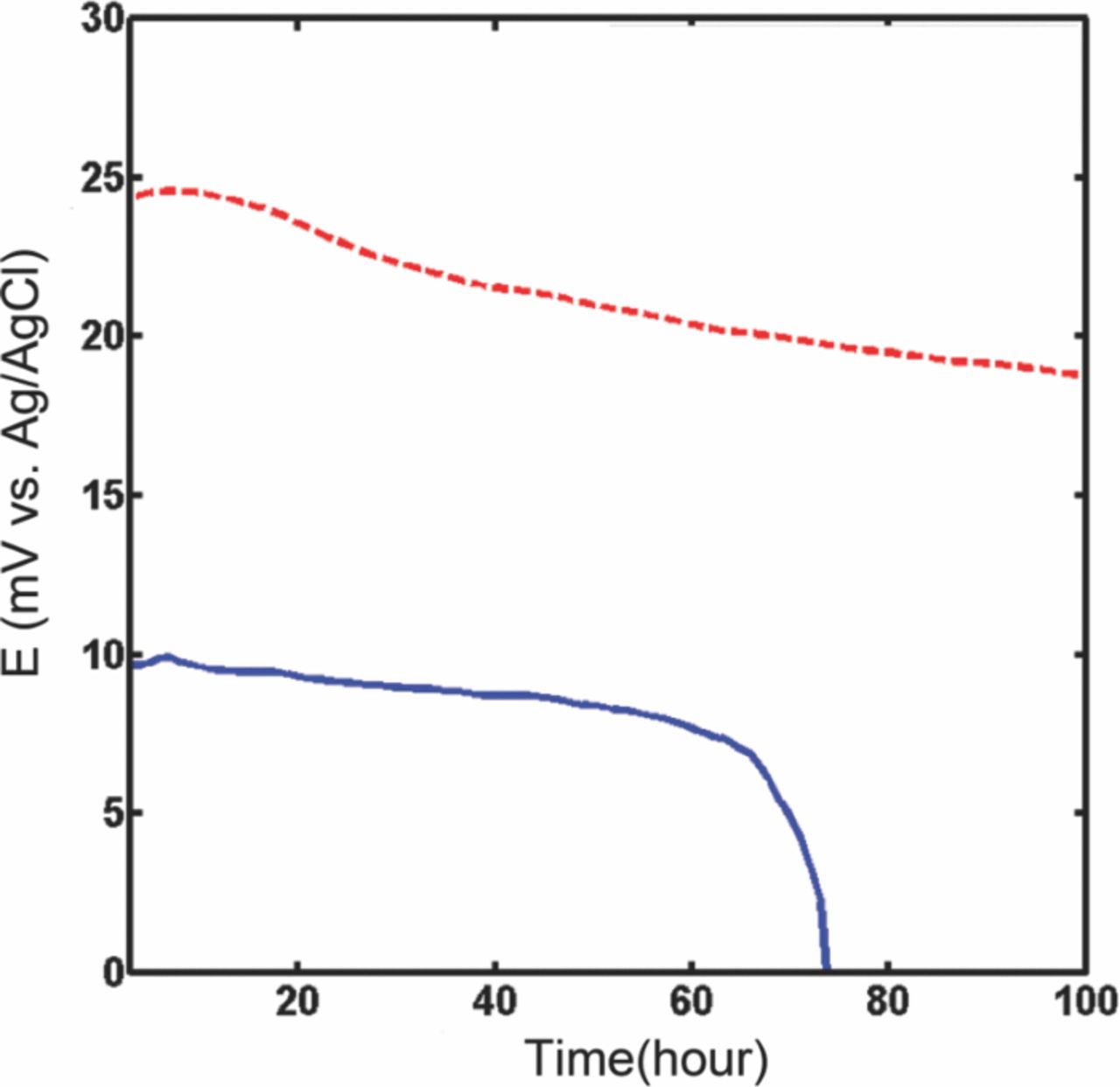
Figure 8. Comparison between microfluidic stationary junction electrode (dashed line) (stability of 45 μV, drift of 5 mV, lifetime of 100 hours) and solid-state electrode (solid line) potentials (stability of 34 μV, drift of 2.2 mV, lifetime of 63 hours) versus standard silver/silver chloride reference electrode in PBS 10X.
The solid-state Ag/AgCl electrode continually degrades in the PBS buffer solution. The equilibrium reaction (equation 1) is driven to the right depending on the Cl− concentration in PBS buffer. The electrode maintains its potential stable until the morphology of electrode's AgCl coverage does not change. Upon any dramatic change, its surface area will change, and consequently, the potential starts to fluctuate more for the test current used to sample the voltage. If the electrode's AgCl content is significantly diminished, then the potential deviates from the Nernst potential (equation 2) and drops rapidly, as evidenced in Figure 8.
Integration of the solid-state Ag/AgCl with a microfluidic channel, on the other hand, can prevent the degradation of the electrode and consequently reduce instability in its potential. In the stationary liquid junction mode of operation of the microfluidic reference electrode, the microchannel is filled with a concentrated internal working electrolyte (inner solution). This configuration keeps the concentration in the proximity of the electrode constant, irrespective of the external solution. It also prevents the dissolution of the AgCl. This stability results in a longer lifetime (see Figure 8).
The stationary liquid junction configuration results in a concentration gradient of chlorine across the membrane if its concentration in the external solution does not match the internal solution (equation 3). For instance, if the external chlorine concentration is small compared to the internal concentration it will result in chlorine diffusion across the membrane. This concentration difference results in a liquid junction potential and its change due to diffusion results in drift of the potential over time. In this case, in addition to AgCl morphology, liquid junction contributes to the electrode stability. One way to overcome this is to use free-diffusion liquid junction format which will be discussed in the next section .
Effect of flow configuration on its potential stability
To do a comprehensive study of microreference electrodes with different configurations, two more modes of operation, in addition to the ones described in previous section, were investigated. As mentioned earlier, one of the limitations microfluidic reference electrode with stationary internal solution is its sensitivity to changes in composition across the liquid junction. To overcome this limitation, the microfluidic reference electrodes with 100 nm pore size membrane and open area of 500 μm × 500 μm with convective flow of internal solution were prepared, pre-conditioned, and tested against a commercial reference electrode according to the protocol described in experimental setup.
The OCPs of the solid-state and the microfluidic reference electrodes are shown in Figure 9. All potentials were offset since the solid-state electrode had a different starting potential as compared to others with internal solution as explained in previous section. As previously stated, the OCP of the solid-state electrode drifts (0.045 mV/hr) throughout its ∼ 67 hrs lifetime with 34 μV hourly averaged fluctuations. On the other hand, the microfluidic electrode with the stationary liquid junction operates in a different fashion in which it maintains its potential stable for 18 hrs and drifts for the rest of its lifetime (82 hrs) with slope of 66 μV/hr and hourly averaged fluctuations of 45 μV. Furthermore, a flow of 1 M KCl through the microchannel (1 μL/min, schematically shown in Figure 7a) reduces the drift for the microfluidic reference electrode from 5 mV to 1.7 mV with hourly averaged fluctuations of 27 μV. However, the flow causes two noticeable instabilities at 75 and 85 hours. In the free-diffusion liquid junction (schematically shown in Figure 7b) 1 M KCl flows through the membrane pores with flow rate of 2 μL/hr. It improves the microfluidic reference electrode from 5 mV to 1 mV drift with hourly averaged fluctuations of 40 μV over 100 hours.
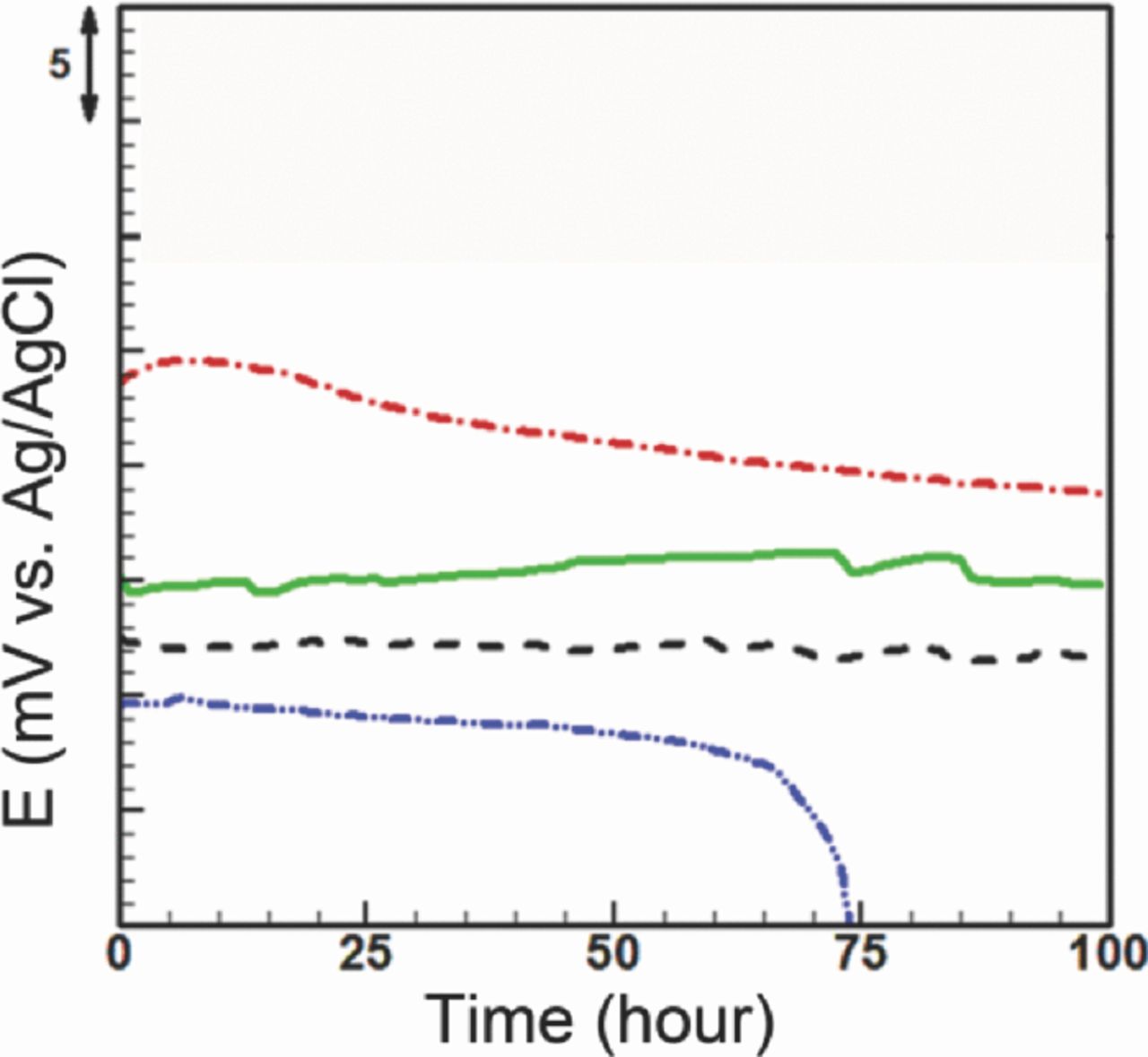
Figure 9. Open-circuit potential measurement between fabricated reference electrodes and standard silver/silver chloride reference electrode in PBS 10X, microfluidic stationary junction electrode (dashed-dotted line): 5 mV drift, 45 μV stability, 100 hours lifetime, microfluidic electrode with internal solution flow in the microchannel (solid line): 1.7 mV drift, 27 μV stability, 100 hours lifetime, microfluidic reference electrode with free-diffusion liquid junction (dashed line): 1 mV drift, 40 μV stability, 100 hours lifetime, solid-state electrode (dashed-double dotted line): 2.2 mV drift, 34 μV stability, 62 hours lifetime.
The stationary liquid junction configuration was found to extend the Ag/AgCl electrode's lifetime (Figure 9) from 63 hours to at least 100 hours. However, the incorporation of a liquid junction introduces instability to the reference electrode's potential, resulting in a higher drift (5 mV). The instability and drift may be due to changes in the liquid junction potential, imposed by the dissolution of the AgCl from the electrode into Ag+ and Cl− in the inner solution. Also, the transport of the external Cl− through the nanoporous membrane to the internal electrolyte can increase the local Cl− concentration outside the liquid junction over time.
Increasing the internal solution concentration results in the reduction of the potential (based on equation 2). Also, changes in the composition of the internal solution can be minimized by flowing the internal solution either through the microchannel or across the membrane, as shown in Figure 9. The flow of internal solution replenishes the surrounding solution of the electrode continuously, thus enabling the electrode to operate consistently during the operation. In the case of a flow of the internal solution in the microchannel, the internal solution concentration can be maintained constant. With a constant internal solution concentration, the drift decreases to 1.7 mV over 100 hours. However, the concentration gradient across the liquid junction continues to change due to the diffusion which keeps hourly averaged fluctuations still high (27 μV). Flowing of the concentrated internal solution (here 1 M) across the membrane lowers drift to 1 mV, over 100 hours. The flow rate used here was found to be optimal in minimizing the solution consumption while still achieving stable potential in this format. Opposite to the case of flow through the microchannel, the hourly averaged fluctuations increase to 40 μV which can be attributed to blockage of nanopores by particulates or AgCl debris. Blockage events will depend on the flow rate, pores size and will accumulate over the duration of operation of the device.
Effect of interface membrane pore size on potential stability
Open-circuit potential measurements of the microfluidic reference electrode with different membrane pore sizes are presented in Figure 10. To investigate the effect of membrane pore size on effusion of internal Cl−, membranes with pore size from 10 to 100 nm were assembled with the stationary liquid junction reference electrodes. The open area of the membrane was kept the same in all experiments (500 μm × 500 μm). The reference electrodes were pre-conditioned and tested against a commercial reference electrode according to the protocol described in experimental section. As demonstrated in Figure 10, there is no significant variation in the hourly averaged fluctuations for reference electrode with different pore sizes (∼30 μV) in a 50 hour period of test.
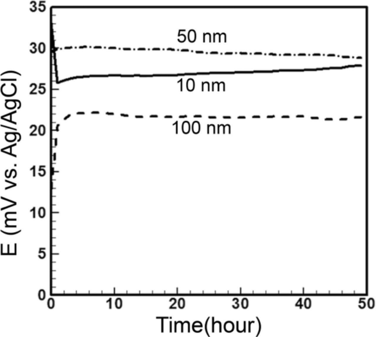
Figure 10. Stability test of microfluidic reference electrode with stationary liquid junction, constant membrane open area of 500 × 500 μm2, and different membrane pore sizes versus standard silver/silver chloride reference electrode in PBS 10X. All pore sizes show ∼30 μV stability while 10 nm shows 1.8 mV drift slightly higher than others' (1.5 mV).
The microfluidic reference electrode with a membrane of pore size of 100 nm has a starting potential of 15 mV, reaching 22 mV in less than an hour, and drifts 1.5 mV to the end of the experiment. The starting potential for the reference electrode with a membrane of pore size 50 nm is 30 mV and drifts 1.5 mV over 50 hours. The one with a membrane of pore size of 10 nm has the starting potential of 34 mV which drops to 26 mV in less than an hour and creeps up slightly to the end of the experiment, making its drift ∼1.8 mV.
A smaller pore size slows down the transport of Cl− ions through the membrane which can prolong the reference electrode's lifetime. However, smaller pores are more vulnerable to clogging. Although the variations in drift among the microfluidic reference electrodes with different pore sizes are not significant, one can attribute a slightly higher drift when using the membrane of 10 nm pore size due to the gradual clogging of the pores by the insoluble AgCl. Therefore, preference is given to the largest pore size that prevents the interface from clogging, i.e., 100 nm pore size.
Effect of Interface Membrane Open Area on Potential Stability
In the next set of experiments, we investigated the effect of membrane open area on effusion of internal Cl−. For these experiments, we used membranes with 100 nm pores. Three membranes with open areas of 300 μm × 300 μm, 500 μm × 500 μm, and 700 μm × 700 μm were assembled with stationary liquid junction reference electrodes. The reference electrodes were pre-conditioned and tested against a commercial reference electrode according to the protocol described in experimental section. As shown in Figure 11, all potentials were offset since the tested reference electrodes showed different starting potentials.
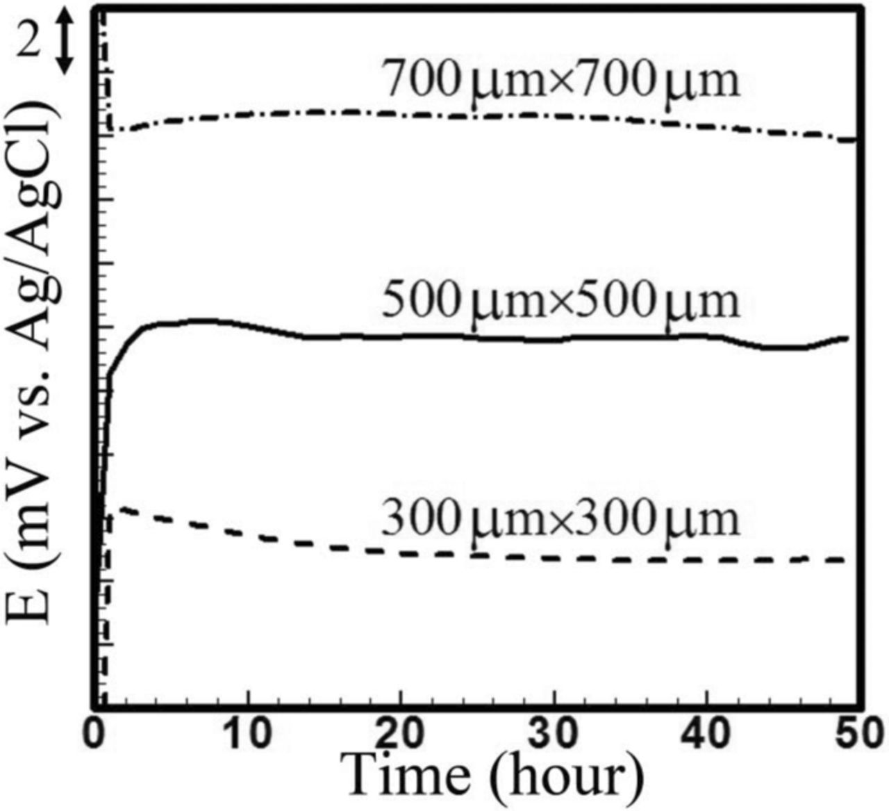
Figure 11. Stability test of microfluidic reference electrode with stationary liquid junction and different open area of 100 nm membrane versus standard silver/silver chloride reference electrode in PBS 10X versus. 700 × 700 μm2 shows 23 μV and the others show 30 μV stability. The drift is 0.8 mV for 300 × 300 μm2 while the other two shows 0.5 mV drift over 50 hours.
The reference electrode with 700 μm × 700 μm open area drifts about 0.5 mV over 50 hours with hourly averaged fluctuations in potential of 23 μV. For the other two open area configurations (500 μm × 500 μm and 300 μm × 300 μm), potentials rise for the first hour of the experiment, and then become stable for the next 49 hours with hourly averaged fluctuations of 30 μV. The former has 0.5 mV drift while the latter shows 0.7 mV drift. Similar to the pore size study, a smaller open area of the membrane is expected to restrict effusion of the internal chlorine. However, according to these results, the open area does not noticeably affect the drift and stability. Therefore, a membrane with 500 μm × 500 μm open area was selected because of its reasonably low drift and small hourly averaged fluctuations.
Effect of external solution pH and chlorine concentration on reference electrode potential stability
The effects of the external pH and chlorine on the solid-state electrode and the stationary liquid junction reference electrode were investigated following the procedure described in experimental section. At each pH or chlorine concentration, the electrode's potential (E) was allowed to stabilize (about 1–3 hours). As seen in Figure 12, the potential of the solid-state Ag/AgCl electrode versus the logarithm of chlorine concentration descends monotonically, starting from ∼110 mV at 10 mM to ∼1 mV at 3 M. In contrast, the stationary liquid junction microfluidic reference electrode potential is insensitive to the external chlorine variations and stays at ∼27 mV. The potential of the solid-state electrode changes in response to the variation of chlorine in the external solution based on the Nernst equation (equation 1). In contrast, the stationary liquid junction microfluidic reference electrode potential is insensitive to the chlorine concentration variations. This insensitivity can be explained by considering the nanoporous membrane as a barrier for the external chlorine to diffuse into the internal solution. It should be noted the experiment was conducted for 1–3 hours (time needed for measurement in BioFET)25 at each concentration. The drift for the stationary liquid junction microfluidic reference electrode over 100 hours was ∼5 mV as shown in Figure 8, which implies very small drift over 1 hour.
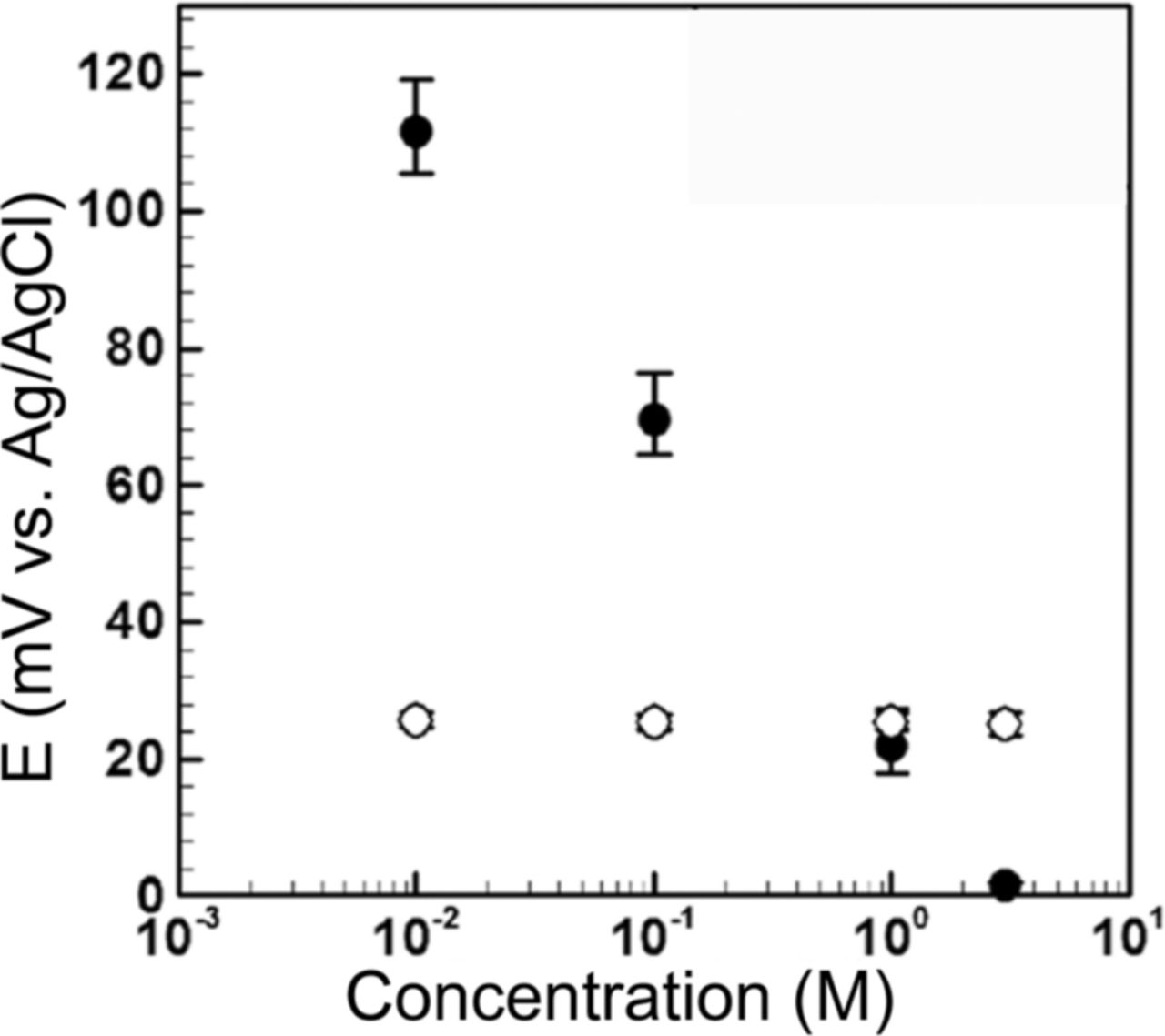
Figure 12. Effect of chlorine concentration of external solution on microfluidic reference electrode with stationary liquid junction (white circles) and solid-state electrode (black circles) stability in KCl as an external solution against standard silver/silver chloride electrode.
In typical biosensing measurement, the operation of the device is around the physiological pH (pH ∼ 7). The polycarbonate membrane used here also dissolves when the pH of the solution is beyond the range of 4–8. Therefore, both the solid-state electrode and the stationary liquid junction microfluidic reference electrode were tested over this range of pH according to the procedure the experimental section. Figure 13 indicates there is a 1.5 mV variation in the bare electrode potential by changing the pH. However, the microfluidic reference electrode with stationary liquid junction demonstrates no sensitivity to the external solution pH variations. Fluctuations in the solid-state electrode can be explained by effect of the pH on the chlorine concentration in the vicinity of the electrode/electrolyte interface. A higher pH value leads to the presence of more OH− (hydroxide ion) and conversion of Ag+ into Ag2O. Subsequently, solubility of the silver chloride increases and the deviation in the potential occurs because of chlorine production. On the other hand, insensitivity of the microfluidic reference to pH variations can be attributed to protective role of the membrane.
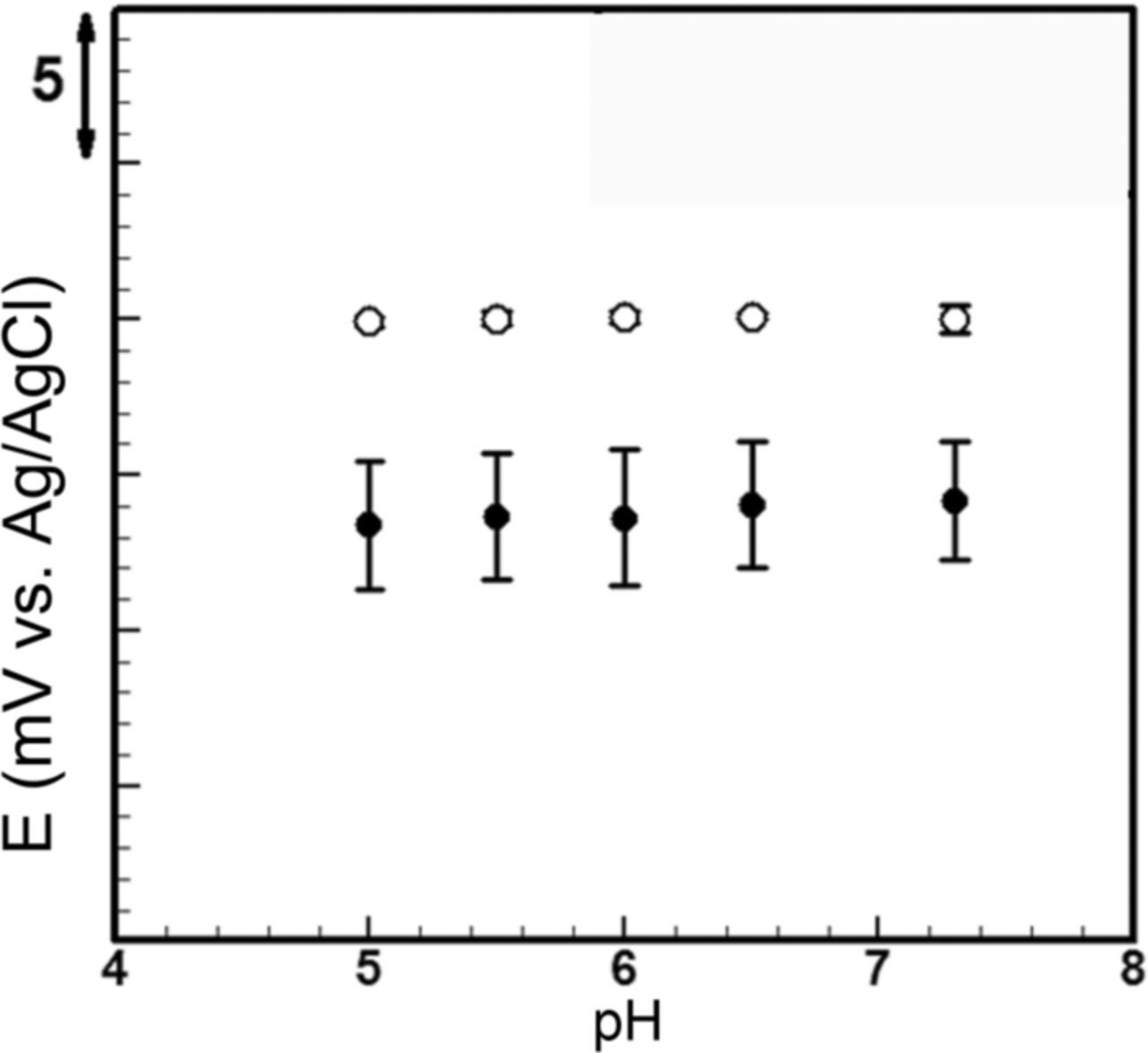
Figure 13. Effect of pH of external solution on microfluidic reference electrode with stationary liquid junction (white circles) and solid-state electrode (black circles) stability in PBS 10X against standard silver/silver chloride electrode. Solid-state electrode potential varies 1.5 mV from pH 5 to 7.3 while microfluidic reference electrode potential stays the same.
Conclusions
We have designed, fabricated, and tested a novel microfluidic Ag/AgCl reference electrode using soft-lithography technique. The stability and lifetime of the solid-state electrode, the stationary liquid junction reference electrode, the reference electrode with flow of the internal solution through the microchannel, and the free-diffusion liquid junction reference electrode were studied. The effect of the pH and chlorine concentration of the external solution on the solid-state electrode and microfluidic reference electrode was also investigated. In terms of stability and lifetime, the open-circuit measurement demonstrated that the free-diffusion liquid junction configuration produces hourly averaged fluctuations (stability) and drift of 40 μV and 1 mV, respectively, over 100 hours. This lifetime is longer than previously reported lifetimes and drift is comparable to previous results. It was also demonstrated that there is no sensitivity to the pH and chlorine concentration of the external solution for the liquid junction microfluidic reference electrode. The planar microfluidic reference electrode, introduced in this paper, can be incorporated with BioFET for medical diagnostic application.
Acknowledgments
Financial support from the Natural Sciences and Engineering Research Council (NSERC) of Canada is acknowledged. PRS also acknowledges support from the Canada Research Chairs Program and the Ontario Ministry of Research and Innovation (OMRI) through their Early Researchers Award. MJD also acknowledges support from the Canada Research Chair program the MEST – Program under Project R31-2008-000-10100-0, South Korea, while he was a Distinguished Visiting Professor in ITCE Division, POSTECH during the final preparations of this manuscript.