
Abstract
The poor workability and the risk of alkali-silica reaction (ASR) caused by alkaline activators restrict the wide range of applications of alkali-activated slag (AAS) cement. This paper presents a study on the effect of fly ash microsphere (FAM) on mitigating the rheological properties and ASR of AAS mortars for the first time. For comparison, the ordinary Portland cement (OPC) mortars blended with FAM are also prepared and investigated. The FAM addition is effective in decreasing the viscosity and meanwhile increasing the fluidity of the AAS pastes and mortars due to its 'ball-bearings' effect. According to the results obtained from the accelerated mortar bar test, the addition of more than 10% FAM reduces the ASR expansion effectively in both of the AAS and OPC mortars. Mineralogical studies demonstrate that for the AAS mortars, FAM promotes the formation of C-A-S-H gel phases with a better alkali binding capacity to mitigate ASR. The pozzolanic reaction of FAM consumes Ca(OH)2 in the OPC mortars, which is essential to the ASR development. In addition, minor ASR products are observed in the AAS or OPC mortars modified with FAM, and meanwhile there is a more strong bonding between the interface of aggregate-paste.
Export citation and abstract BibTeX RIS

Original content from this work may be used under the terms of the Creative Commons Attribution 4.0 licence. Any further distribution of this work must maintain attribution to the author(s) and the title of the work, journal citation and DOI.
1. Introduction
In the production of Portland cement, high-temperature calcination of limestone is required to decompose to form the reactive silicate and aluminate phases. The CO2 emitted during this process accounts for about 6%–7% of the total global annual carbon emissions [1]. And a series of durability problems that may occur subsequently make it necessary to develop a new type of environmentally friendly building cementitious material with reliable performances [2, 3]. In recent decades, alkali-activated blast furnace slag (AAS) cement attracts great attention in the application prospects of construction and building materials owing to its relatively lower carbon footprint than the traditional ordinary Portland cement (OPC) [4–6]. The formation of aluminum-modified calcium silicate hydrate (C-A-S-H) gel phase brings excellent properties to the AAS binder, such as the rapid strength development, low permeability and good thermal stability. However, to achieve these optimal properties, the alkaline silicate solution with high concentration is commonly used as the activator to produce the AAS products, which is easy to induce the alkali-silicate reaction (ASR).
Alkali-silica reaction (ASR) is a severe durability problem faced by the OPC concretes all over the world [7]. The reaction between the reactive silica in aggregates and alkalis in the pore solution leads to the formation of alkali-silica gel phase with expansive pressure, which will raise the concern of deterioration and cracking issues in the concrete structure [8–10]. The presence of Ca2+ ions in the system is also essential for the formation of ASR products with swelling performance [11, 12]. The formation of a semi-permeable layer around the reactive aggregates allows the OH− ions to penetrate in to form the ASR gel, which results in the development of swelling pressure under the layer [13]. Compared with OPC, the higher alkalinity in AAS binder seems to increase the susceptibility to ASR deterioration, although there is still much controversy [14–16]. Moreover, the high calcium content supplied by slag may seems to contribute to the severe swelling performance of ASR gel phase formed in the AAS binder.
Alkaline activators may cause skin burns and respiratory diseases of workers during construction, as well as the potential risk of ASR deterioration in the later use [6, 17, 18]. In addition, its highly viscous property also leads to the poor rheology and workability performance of AAS products [19]. The chemical instability of organic superplasticizers in highly alkaline environment makes the common superplasticizers based on polycarboxylate, melamine, vinyl copolymer and naphthalene used in OPC system lose their fluidizing role in AAS system [20, 21]. Thus, there is an urgent need for the development of effective superplasticizers and rheological control admixture through particle geometry effects [22]. Fly ash microsphere (FAM) is a class of superfine fly ash spherical particles with an average particle size of a few microns. It is generally gathered from the smoke of coal combustion in the furnace at around 1800 °C [23]. Due to its relatively higher sphericity and smaller particle size compared with the ordinary fly ash, FAM has received great attention from many researchers as fine supplementary cementitious material (SCM) in OPC and AAS products [24]. Kwan et al [25] studied the effects of FAM on rheology, adhesiveness and strength development of OPC mortars, and found that the addition of FAM could facilitate the formation of water films coating the solid particles by increasing the packing density. Wang [26] incorporated FAM as an ultra-fine SCM in the high-strength concrete (HSC) and observed the positive role in compacting the pore structure. Yang et al [23] took advantage of the 'ball-bearings' effect of FAM in sodium silicate-activated fly ash-slag pastes to effectively reduce the plastic viscosity.
Simultaneously, the addition of FAM can work as a kind of specific fly ash precursor in the AAS system. García-Lodeiro [27] investigated the ASR of alkali-activated fly ash (AAFA) mortars by using the fine aggregates with different degrees of reactivity, and concluded that AAFA system was more resistant to the ASR deterioration than the OPC system. Li et al [28] made a comparative study of ASR occurred in the AAS, AAFA and OPC concretes according to ASTM C1567 and C1293 standard tests. It was observed that the AAS concrete even experienced with a significant ASR expansion with the addition of non-reactive aggregates, while AAFA with ASR reactive aggregates exhibited minor expansion. This means that more alumina species dissolved from fly ash is effective in reducing the ASR deterioration of the AAS system. Therefore, it seems that the FAM addition in AAS system will not only enhance the workability but also mitigate the ASR expansion. However, a detailed investigation of the influence of FAM on the performance of AAS mortars is not yet available.
This paper aims to investigate the rheological properties and ASR expansion of sodium silicate-activated slag mortars modified with FAM. The FAM-modified OPC mortars are also analyzed to perform a comparative study. The rheological measurement of pastes and the fluidity test of mortars were both performed. The accelerated mortar bar test following the procedure described in ASTM C1260 [29] was conducted to determine the ASR expansion of mortars. To better understand the phase evolution and microstructure development in the mortars, other characterizations were conducted, such as x-ray diffraction analysis (XRD), Fourier transform infrared spectroscopy (FTIR), thermogravimetric analysis (TGA) and SEM-EDS. The core innovation of this work is the first exploration of the effects of FAM on ASR deterioration in AAS mortars. At the same time, accompany with investigating the influence of FAM on rheological properties of AAS mortars is obviously meaning for achieving the application of this material in construction industry.
2. Experimental
2.1. Materials
Ground granulated blast-furnace slag and P II 525 ordinary Portland cement (OPC) were supplied by Jingtaicheng Environmental Resources Co., Ltd (Shahe, China) and Jiangnan-Onoda cement co., Ltd (Nanjing, China) respectively. Fly ash microsphere (FAM) was a class of superfine spherical-shaped particles collected from the exhaust smoke of coal-fired power station by using the electrostatic adsorption classifier technology. The particle size distribution (PSD) of the slag, OPC and FAM were tested by the laser particle size analyzer, and the results are shown in figure 1. The particle size of FAM, with the mean particle size (D50) of 1.89 μm, is much smaller than slag and OPC. The chemical compositions of these materials as detected by x-ray fluorescence (XRF) are summarized in table 1. Compared to slag and OPC, FAM contains less content of CaO and more SiO2. Their XRD patterns are shown in figure 2. Except for the crystalline phase of calcium silicate, FAM is highly amorphous. The much smaller particle size and the amorphous property make FAM exhibit the higher pozzolanic activity than ordinary fly ash [30–32]. The morphologies of slag, OPC, and FAM particles collected by using SEM are shown in figure 3. Both slag and OPC particles exhibit irregular angular shapes, while the FAM particles have smooth surface and ultra-high sphericity.
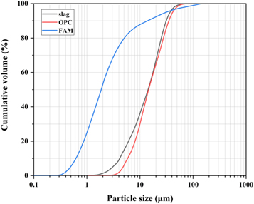
Figure 1. Particle size distribution of slag, OPC and FAM.
Download figure:
Standard image High-resolution imageTable 1. Chemical compositions (wt%) of the slag, OPC and FAM as measured by XRF. LOI is loss on ignition at 1000 °C.
| Materials | SiO2 | Al2O3 | CaO | MgO | Fe2O3 | K2O | TiO2 | Na2O | LOI |
|---|---|---|---|---|---|---|---|---|---|
| Slag | 31.28 | 15.59 | 41.55 | 8.05 | 0.40 | 0.42 | 0.82 | 0.46 | 1.41 |
| OPC | 19.02 | 4.77 | 63.42 | 1.87 | 3.29 | 1.06 | 0.30 | 0.14 | 1.37 |
| FAM | 54.55 | 14.55 | 12.47 | 4.53 | 4.62 | 2.71 | 0.77 | 2.59 | 0.95 |
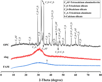
Figure 2. XRD patterns of slag, OPC and FAM.
Download figure:
Standard image High-resolution image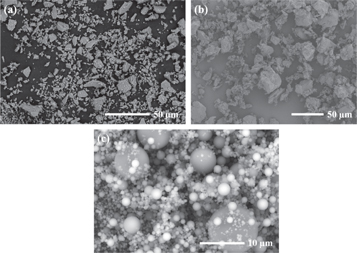
Figure 3. SEM images of (a) slag, (b) OPC and (c) FAM.
Download figure:
Standard image High-resolution imageAlkaline activators were prepared by blending sodium hydroxide pellets (≥96 wt% purity) with sodium silicate solution (SiO2 = 32.35 wt%, Na2O = 13.73 wt%) and deionized water to reach the required modulus of 1.6 (SiO2/Na2O molar ratio) and concentration (SiO2 + Na2O mass fraction in the solution) of 30%. Activators were prepared 24 h prior to mixing in order to allow the activators to reach ambient temperature.
ISO standard sand (with fineness modulus FM = 2.6–2.8) was used as the fine aggregates to prepare the AAS and OPC mortars. This sand is commonly used to evaluate the strength of cement products in China.
2.2. Mortars preparation
The mix proportions of AAS and OPC mortars are shown in table 2. The slag and the cement were replaced by FAM at 0%, 5%, 10%, 15% and 20% by mass of the total binders, respectively. All mortars were prepared with a constant sand/binder ratio of 2.25 (by mass), while the activator/slag ratio of the AAS mortars and the water/cement ratio of the OPC mortars were set as 0.58 and 0.47 (by mass) respectively, which could provide a good workability during mixing. Mortar specimens were cast into 30 × 30 × 30 mm cubic molds for testing the compressive strength and 20 × 20 × 80 mm cuboid molds for testing the linear volume change, respectively. After casting, mortar specimens sealed in the molds were stored in a standard curing room at 20 ± 2 °C with relatively humidity above 95% for 24 h. Thereafter, mortar specimens were carefully demolded and immediately submerged in 1 mol l−1 NaOH solution at ambient temperature for 6 h, after which the initial length of the specimens were measured using a digital length comparator with the accuracy of ± 0.01 mm.
Table 2. Mix proportions of AAS and OPC mortars (wt%).
| Mixture Codes | Slag | OPC | FAM | Activator | Water | Aggregate |
|---|---|---|---|---|---|---|
| AAS0 | 100 | — | 0 | 58 | — | 225 |
| AAS5 | 95 | — | 5 | 58 | — | 225 |
| AAS10 | 90 | — | 10 | 58 | — | 225 |
| AAS15 | 85 | — | 15 | 58 | — | 225 |
| AAS20 | 80 | — | 20 | 58 | — | 225 |
| OPC0 | — | 100 | 0 | — | 47 | 225 |
| OPC5 | — | 95 | 5 | — | 47 | 225 |
| OPC10 | — | 90 | 10 | — | 47 | 225 |
| OPC15 | — | 85 | 15 | — | 47 | 225 |
| OPC20 | — | 80 | 20 | — | 47 | 225 |
2.3. Experimental methods
2.3.1. Rheological properties
2.3.1.1. The fresh pastes
Referring to GB/T 22235–2008 [33], the apparent viscosity of the fresh pastes with the same mixture proportions (table 2) was tested by using a SHP NDJ-8S model viscometer. It is a rotational viscosimeter with a smooth-walled concentric cylinder. Considering that both the AAS and OPC pastes belong to the category of non-Newtonian fluids, a fixed No. 3 rotor was selected with a speed of 12 r/min, and the measuring range was 0–10 Pa·s. All the viscosity values were recorded at the fifth minute after stirring.
To determine the fluidity of fresh pastes, mini-slump test was also conducted according to GB/T 8077-2012 [34]. A mini-slump cone (height 60 mm, top diameter 36 mm and bottom diameter 60 mm) was placed at the center of a slightly wetted glass plate, and the fresh pastes was poured into the cone until it was full. Lift the cone softly and measure the maximum diameter of the flowing part in two directions perpendicular to each other. Take the average value as the fluidity of pastes.
2.3.1.2. The fresh mortars
The slump test of fresh mortars was carried out with a jump table following the standard of GB/T 2419-2005 [35]. Firstly, the mixed mortars were casted into the conical mold (height 60 mm, top diameter 70 mm and bottom diameter 100 mm) with two layers. Next, the mold was lifted vertically and the jump table was vibrated for 25 s at the vibration frequency of 1 s−1. After the vibration, the diameters of the mortar were measured in two perpendicular directions with calipers and the average value was took as the fluidity for the tested mortars.
2.3.2. Accelerated mortar bar test
The accelerated mortar bar test was performed according to the procedure as described in ASTM C1260 [29]. All mortar specimens after the initial length measurement were placed in a sealed plastic container, which contained 1 mol l−1 NaOH solution, and then cured in the water bath at a constant temperature of 80 °C. When the curing age reached up to 1, 3, 5, 7, 10, 14, 21, 28, 35, 42, 49 and 56 days, the container was removed from the water bath and cooled at room temperature for 6 h to avoid the influence of high temperature on the test results. The length of specimens was measured and recorded. Each average expansion value was obtained from four specimens for the same mixture.
2.3.3. Compressive strength
The AEC-201-type automatic cement strength testing machine was used to test the compressive strengths of the 30 × 30 × 30 mm cubes. After demolding, all of these specimens were divided into two parts. One part was steam curing at 80 °C, and another part was cured in 1 mol l−1 NaOH solution at 80 °C for 56 days, with the same curing conditions of those specimens for accelerated mortar bar test. In order to ensure the accuracy of the data, three replicate specimens were measured for each mixture to take the average values.
2.3.4. Microstructural and mineralogical characterization
After the alkali exposure at 80 °C for 56 days, the mortar specimens were cored, broken, submerged in isopropanol for 48 h, and then dried in a vacuum oven at 40 °C for 24 h to stop hydration. The mortars were crushed and ground to the powder, and then measured for the x-ray diffractometry (XRD), thermogravimetric analysis (TGA), and Fourier transform infrared spectroscopy (FTIR) characterizations. The Rigaku D max/RB machine was used to conduct the XRD analysis with Cu Ka radiation at a scanning rate of 10° min−1 from 8° to 80° 2θ. The TGA STA 449 C analyzer (NETZSCH) was used to conduct the TGA with a heating rate of 10 °C min−1 in nitrogen atmosphere from 30 °C to 1000 °C. The Thermo Nicolet Nexus FTIR instrument was used to conduct the FTIR analysis via KBr pellet technique, with scanning from 4000 cm−1 to 400 cm−1.
The fractured mortars were casted with a low viscosity epoxy, polished with diamond sandpaper, and coated with gold. The morphology of mortar was analyzed using a FEI Quanta FEG 650 environmental filed emission scanning electron microscope (FE-SEM) in the BSE mode at 10 kV accelerating voltage and 10 mm working distance. An equipped energy dispersive spectroscopy (EDS) was also used to conduct elemental composition analysis.
3. Results and discussion
3.1. Rheological properties
Figure 4 shows the variations in apparent viscosity and fluidity of the fresh AAS and OPC pastes with different dosages of FAM, respectively. For AAS pastes (figure 4(a)), the liquid-solid ratio of 0.58 makes them show greater fluidity compared to OPC pastes. It is noted that as the amount of slag replacement by FAM increases from 5% to 20%, the apparent viscosity of the pastes decreases by 75.4%, and meanwhile the fluidity increases by 27.8%. There is a strong correlation between the apparent viscosity and fluidity of AAS pastes. Contrary to AAS pastes, with the incorporation of FAM, the apparent viscosity of OPC pastes gradually increases (figure 4(b)). This seems to be attributed to the high specific area and water absorption potential of FAM particles in the OPC paste. The fluidity firstly increases and then decreases as the FAM content increases from 5% to 20%. Compared with AAS pastes, the incorporation of FAM has little effect on controlling the apparent viscosity and fluidity of OPC pastes. It is probably due to that the excessive water present in OPC system weakens its dependence of rheological properties on the performance of inter-particle contacts and friction. The similar phenomena are also reflected in fresh AAS and OPC mortars. As shown in figure 5, the incorporation of 20% FAM improves the fluidity of AAS mortars by 19.1%, but is nearly invalid in the OPC mortars. In addition, by comparing the changes in the fluidity of AAS and OPC systems before and after adding sand, it can be found that the high-viscosity alkaline activators can make the sand particles adhere closely to each other, thereby greatly weakening the fluidity of AAS mortars.
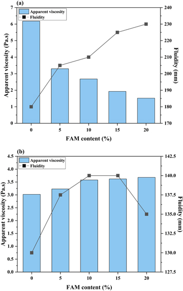
Figure 4. The effects of FAM content on the apparent viscosity and fluidity of (a) AAS and (b) OPC pastes.
Download figure:
Standard image High-resolution image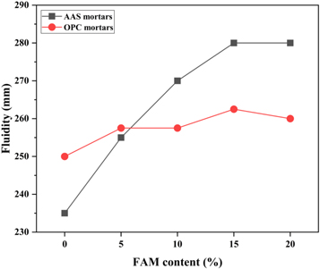
Figure 5. The effects of FAM content on the fluidity of AAS and OPC mortars.
Download figure:
Standard image High-resolution imageIt is generally accepted that the viscosity is one of the major rheological properties, and a greater fluidity always indicates a better workability. The addition of an appropriate amount of FAM is an effective way to improve the rheological properties of the AAS system. The FAM particles with extremely high sphericity and smooth surfaces work as ball-bearings among the slag particles with irregular angular shapes to enable the effective sliding [23]. This speculation can be proved by the BSE image shown in figure 6. The angular slag particles and even the aggregates are surrounded by the superfine FAM particles embedded in the matrix, which play the ball-bearings role for enhancing the fluidity of the AAS paste and mortar. In addition, the FAM particles fill in the interstitial voids of the binder instead of the activators or water, resulting in an increase in the amount of excess water available for forming water films [36]. An increase in the thickness of water films is helpful in reducing the internal fractions between the angular slag particles.
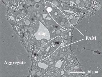
Figure 6. The BSE image of the mortar specimen containing FAM particles.
Download figure:
Standard image High-resolution imageThe rheological characteristics of fresh pastes and mortars depend on a series of factors of the powders, such as particle shape, surface morphology, specific surface area and particle size distribution. Felekoğlu and Ferraris [37, 38] explored the possibility of using ordinary fly ash and grinded ultrafine fly ash to improve the rheology of cement pastes, mortars and concretes. However, the cluster of microspheres and the unburned carbon with porous structure presented in the ordinary fly ash determine its pseudo-coarse nature, thereby increasing the water demand during the wetting process. For the ultrafine fly ash, the sphericity has been broken up during the ball milling process, which weakens the 'ball bearings' effect. In comparison, the FAM used in this paper is a ultrafine fly ash microsphere captured directly from the exhaust smoke of coal combustion in the furnace at around 1800 °C. The higher combustion temperature is helpful in removing the unburned flocculent organic matters [39]. The complete sphericity and the smooth surface texture can exhibit a better performance in reducing the friction between particles inside the system when compared with the ordinary fly ash and grinded ultrafine fly ash. In addition, the particle packing model can also be optimized by the FAM due to its finer particle size (1.89 μm) [30]. This facilitates the release of excess water locked by the pores to form water films.
3.2. ASR expansion
The ASR expansion of AAS and OPC mortars containing different amounts of FAM is shown in figure 7. The FAM addition effectively reduces the ASR expansion in both AAS and OPC mortars. The 14-day expansion ratios of AAS mortars decrease from 0.136% to 0.057% as the increase of FAM content. According to the ASTM C1260 standard [29], the expansion ratios of AAS mortars with 0–10% FAM content exceed the 14-day threshold of 0.1% (figure 7). In comparison to the AAS mortars, the 14-day expansion ratios of all OPC mortars are below the 0.1% threshold. The AAS mortars have higher ASR expansion than the OPC mortars. Lindgård et al [40] suggested that the high alkali content in the pore solution enhanced the ASR reactivity of the silica components in the sands. The 15% and 20% FAM addition in OPC mortars are more effective in reducing the ASR expansion than in the AAS mortars. With the 20% FAM addition, the 56-day expansion ratios of OPC mortars decreases from 0.398% to 0.139%, while the ratios in AAS mortars decrease from 0.476% to 0.340%. This is probably also due to the higher alkalinity in AAS mortars. The above results show that FAM has the equivalent effect as ordinary fly ash in restricting the ASR expansion. Turk [41] replaced the cement with 30% fly ash to reduce the 14-day expansion ratios of OPC mortars made of high reactivity aggregates from 0.454% to 0.303%. Shi et al investigated the role of low-calcium fly ash in mitigating ASR of AAS mortars, and found the optimum dosage of fly ash was 30% to reduce the ASR expansion [42].

Figure 7. The effects of FAM content on ASR expansion of (a) AAS and (b) OPC mortars after 56 days of exposure in 1 mol l−1 NaOH solution at 80 °C.
Download figure:
Standard image High-resolution image3.3. Compressive strength
The effects of FAM addition on compressive strengths development of mortars under different curing conditions are shown in figure 8. One set of specimens were performed with the steam curing at 80 °C and another set of specimens was submerged in 1 mol l−1 NaOH solution in a sealed plastic container at 80 °C.
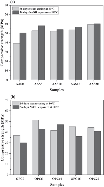
Figure 8. The effects of FAM content on compressive strengths of (a) AAS and (b) OPC mortars performed with different curing conditions.
Download figure:
Standard image High-resolution imageAs shown in figure 8(a), the compressive strengths of AAS mortars increase with the increasing content of FAM, regardless of the exposure conditions. The high specific surface area of FAM particles leads to the high reactivity and filling effect in the binder. Moreover, there was an increase in the strength after the alkali exposure. This is attributed to the secondary activation of the unreacted slag and FAM particles during the exposure in the 1 mol l−1 NaOH solution, as discussed in previous literatures [43, 44]. Other researchers also attributed the strength increase to that the formation of ASR gel with certain viscosity precipitates into the gaps between the matrix and fine aggregates to promote the adhesion performance [45–47].
However, the OPC mortars immersed in the 1 mol l−1 NaOH solution generally exhibit lower compressive strengths than the mortars with 80 °C steam curing, as shown in figure 8(b). The reason behind the strength loss is the deterioration of mortar specimens caused by ASR expansion. The FAM addition could also enhance the compressive strength of OPC mortars under both curing conditions. It should be noted that OPC mortar with 10% FAM content after the alkali exposure even exhibits a higher compressive strength than the that after steam curing. This means the FAM addition mitigates the strength degradation due to ASR deterioration.
Compared with OPC mortars, the higher ASR expansion does not cause any degradation in compressive strengths of the AAS mortars. Similar results were also found in the research conducted by Shi et al [44]. On the one hand, the secondary activation of the unreacted slag and FAM particles in the AAS system by the penetration of OH− ions is the main reason behind this phenomenon. On the other hand, although the 14-day expansion ratios of AAS mortars exceed the threshold value specified in ASTM C1260, the expansion does not cause any visible microcracks on the surface of the specimens. The rapid early-age alkali-activated reaction in the AAS binder results in the formation of compact pore structure and the excellent mechanical properties [48]. The ASR expansion below a certain value is insufficient to bring about the deterioration in the AAS mortar structures to cause the loss of compressive strengths.
3.4. XRD analysis
Figure 9 shows the XRD patterns of the selected mortars of AAS0, AAS15, AAS20, OPC0, OPC15 and OPC20 after 56 days of alkali exposure at 80 °C. The diffractograms are dominated by the quartz reflection obtained from the sand aggregates. For the AAS mortars, the broad peak at ∼29° 2θ can be well related to C-A-S-H gel phase, which is also known as tobermorite [49]. Due to its lower amounts of Ca and more amounts of Al in tetrahedral locations, C-A-S-H gel has a higher degree of polymerization and crosslinking between the formed gel chains than C-S-H gel phase [18]. The peaks centered at 27.5° 2θ in AAS15 and AAS20 are assigned to the newly formed aluminosilicate zeolite gismondine, which is usually identified in the binders with high aluminum environment [50, 51]. Previous literatures [52, 53] reported that the C-A-S-H gel phase with lower Ca/Si and higher Al/Si ratios had a better binding capacity for alkalis than the C-S-H, accompanied by reducing the alkalinity of the pore solution for hindering the ASR to a certain extent. Portlandite (Ca(OH)2) and Calcium silicate Hydrate (C-S-H) are the main phases detected in the OPC mortars. The incorporation of FAM does not cause any other change in the mineral phase, except for the increase in intensity associated with quartz reflection. In addition, no characteristic diffraction peak of ASR products is observed in AAS or OPC mortars, because of the limited quantity and relatively poor crystallinity of the nano-size ASR products [54, 55].
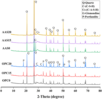
Figure 9. XRD patterns of AAS and OPC mortars as a function of FAM content after 56 days of exposure in 1 mol l−1 NaOH solution at 80 °C.
Download figure:
Standard image High-resolution image3.5. TG analysis
Figures 10 and 11 show the DTG curves and mass loss fractions of AAS and OPC mortars after 56 days of alkali exposure. The main endothermic peak present below 250 °C is assigned to the physically and chemically bond water loss from the pore network and the interlayers of C-A-S-H gel structures [56]. For the AAS mortars, it should be noted that this peak seems to shift towards higher temperature for the mortars incorporated with FAM. This phenomenon can be attributed to the formation of the gels with more tightly bonded water and the compact microstructure due to the filling effect of FAM. The mass loss friction below 250 °C increases firstly and then decreases with the increasing content of FAM, as shown in figure 11(a). This is probably attributed to that the excessive FAM will dilute the reactive calcium content obtained from slag particles and affect the formation of C-A-S-H gel phase [23]. The endothermic peak at 330 °C–400 °C is attributed to the dihydroxylation and the interlayer anions removal from the Mg-Al hydrotalcite-like phase formed in the AAS binder [57]. In theory, the presence of hydrotalcite-like phase also contributes to the mass loss at around 180 °C, which was overlapped with the decomposition temperature of hydration products [58]. There is also a small endothermic peak caused by the decomposition of portlandite (Ca(OH)2) located at around 420 °C–500 °C. The mass loss fraction decreases with increasing FAM content. It indicates that more portlandite is consumed progressively during the reaction of FAM, which contains relatively lower amount of calcium than the slag. The small peak among the range of 600 °C–700 °C is related to the decomposition of carbonate phases. No obvious variation tendency is observed in the AAS mortars.
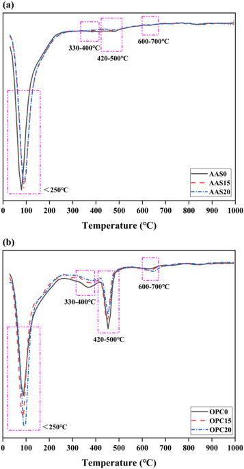
Figure 10. DTG curves of (a) AAS and (b) OPC mortars after 56 days of exposure in 1 mol l−1 NaOH solution at 80 °C.
Download figure:
Standard image High-resolution image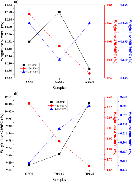
Figure 11. Mass loss fractions at different temperature regions of (a) AAS and (b) OPC mortars after 56 days of exposure in 1 mol l−1 NaOH solution at 80 °C.
Download figure:
Standard image High-resolution imageComparing with the AAS mortars, the DTG curves of the OPC mortars have four distinct endothermic peaks, as shown in figure 10(b). The first endothermic peak at temperature below 250 °C corresponds to the dehydration reactions of several hydrates (C-S-H, carboaluminates, ettringite, etc) [59]. The addition of the FAM significantly increases the peak intensity, and thus increases the mass loss fraction below 250 °C (figure 11(b)). This means that the FAM addition promotes the formation of the hydration products. Due to the high calcium content in the OPC system, the endothermic peak located at 300 °C–400 °C can be attributed to the thermal decomposition of the Ca-Al layered double hydroxides (LDHs), also referred to the AFm phases. The third endothermic peak at around 420 °C–500 °C is associated with the decomposition of portlandite. The peak in C100 is much more intense than the peaks in other mortars. Moreover, the mass loss fraction in this portlandite peak decreases as the content of FAM increases. It indicates that the pozzolanic reaction of FAM may consume Ca(OH)2 to generate additional hydration products in the matrix [26, 59]. The fourth endothermic peak located at 600 °C–700 °C is assigned to the decarbonation of CaCO3. The mass loss fraction in this peak also increases with the content of FAM. This is probably due to that CO3 2− can be absorbed strongly on the interlayer surfaces of LDHs and AFm phase in OPC mortars [60, 61].
3.6. FTIR analysis
As shown in figure 12, FTIR tests are carried out for the selected AAS and OPC mortars after 56 days of alkali exposure. The bending vibration band of H-OH bonds at 1600–1700 cm−1 and the symmetrical stretching vibration band of H-OH bonds at 3441 cm−1 are both attributed to the water absorption in the reaction products [56, 62]. For the OPC mortars, there is a band situated at 3642 cm−1, which is assigned to the stretching vibration of O-H bonds in Ca(OH)2 (figure 12(b)) [63]. As a consequence of the weathering during samples preparation, the band at 1407 cm−1 is associated with the asymmetric stretching vibration mode of O-C-O bonds in the carbonate group (CO3 2−) of calcite [64]. For all the mortars, there are two double bands appearing on the spectra at 1079 cm−1 / 974 cm−1 and 797 cm−1 / 778 cm−1. Among them, the double band located in the range of 1200–900 cm−1 is attributed to the stretching vibration mode of Si-O-T bonds (T = Si, Al) in the silicate groups [56, 65]. It is worth noting that the intensity of the band at relatively low wavenumber (974 cm−1) increases with the incorporation of FAM in AAS mortars (figure 12(a)). This can be explained by the formation of Al-rich type aluminosilicate gel. The lower force constant of Al leads to lower vibration frequencies of Al-O bonds than Si-O bonds. Different from the AAS mortars, the signals obtained at 1079 cm−1 in the OPC mortars with FAM addition are much sharper than that in neat OPC mortar (figure 12(b)). This indicates that the effective dissolution of the reactive silica species in FAM enhances the polymerization degree of C-S-H gel phase formed in the OPC mortars [66]. This speculation is also confirmed by the increase in the band intensity at 693 cm−1 assigned to bending vibration of Si-O-Si bonds. The other double band at 797 cm−1 and 778 cm−1 corresponding to quartz is also present in the FTIR spectra [67]. The band at 459 cm−1 is related to the internal deformation vibration of SiO4 tetrahedra [62, 68].
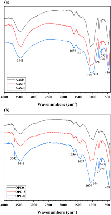
Figure 12. FTIR spectra of (a) AAS and (b) OPC mortars after 56 days of exposure in 1 mol l−1 NaOH solution at 80 °C.
Download figure:
Standard image High-resolution image3.7. SEM-EDS analysis
Figure 13 shows backscattered electron (BSE) images obtained from the polished surfaces of the selected AAS mortars after alkali exposure for 56 days. As shown in figure 13(a), the layered ASR products are observed inside the microcracks present in the aggregate. These microcracks appears to be formed due to the swelling pressure developed from the hygroscopic ASR gels, which absorb moisture from the surrounding pore solution [10]. Consequently, this is one of the main reasons for the relatively large volume expansion and compressive strength variations of the AAS mortars after alkali exposure. For the AAS15 mortar, it is noticeable that the FAM particles co-exist in the matrix with remnant slag particles (figure 13(b)). Although there are still some microcracks inside the aggregates, no obvious ASR products is observed in the AAS15 mortar. When the content of FAM reaches 20%, the aggregate in the mortar keeps integrity and no obvious microcracks is observed (figure 13(c)). This confirms the effectiveness of FAM in mitigating ASR in the AAS mortars.
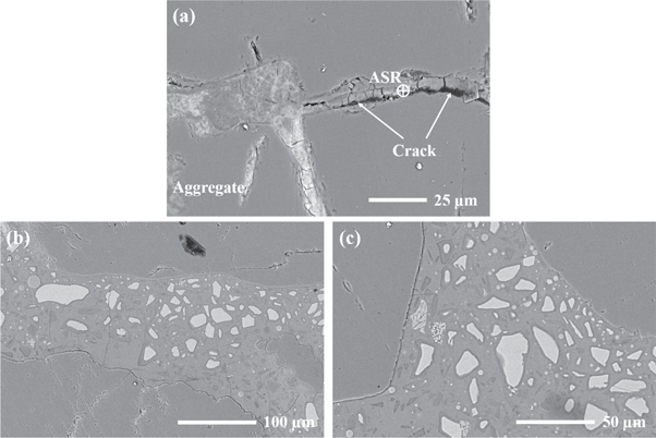
Figure 13. BSE images of AAS mortars after 56 days of exposure in 1 mol l−1 NaOH solution at 80 °C: (a) AAS0; (b) AAS15; (c) AAS20.
Download figure:
Standard image High-resolution imageThe similar ASR mitigation effect is also observed in the OPC mortars modified with FAM, as shown in figure 14. Due to the swelling of ASR gels, the severe crack extends from the edge to the interior of the aggregate (figure 14(a)). Moreover, the fragmented aggregate-binder interface is also observed in the mortar. This matches well with the relatively lower compressive strength of OPC mortars after the alkali exposure. The OPC15 and OPC20 mortars shows more complete aggregate structures, even though considerable number of cracks still exist in the paste (figures 14(b) and 14(c)).
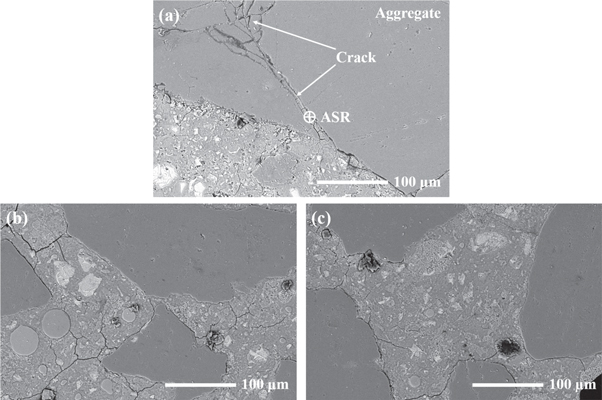
Figure 14. BSE images of OPC mortars after 56 days of exposure in 1 mol l−1 NaOH solution at 80 °C: (a) OPC0; (b) OPC15; (c) OPC20.
Download figure:
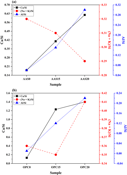
Standard image High-resolution imageTo better understand the effects of FAM addition on the phase evolution of ASR products, elemental analysis using energy dispersive spectrometry (EDS) was conducted. Table 3 summarizes the average elemental compositions and atomic ratios calculated from the three or four spots of the ASR products detected in the interior of aggregate. As reported in previous literatures [40, 69], the chemical compositions of ASR products are rich in silica with a certain amount of alkalis (e.g. Na, K), as well as calcium. The compositions varied with the location of ASR products in the mortars [40, 69]. The Ca/Si and (Na + K)/Si ratios of the ASR products in AAS mortars are in the ranges of 0.18–0.62 and 0.29–0.32 respectively. For the OPC mortars, the Ca/Si and (Na + K)/Si ratios are in the ranges of 0.13–1.40 and 0.35—0.41, respectively. The effects of FAM content on atomic (Na + K)/Si, Ca/Si and Al/Si ratios are also shown in figure 15. For the AAS mortars, the FAM addition increases the Ca/Si ratios, but slightly decreases (Na + K)/Si ratios (figure 15(a)). This suggests that the FAM consumes alkali hydroxides in the pore solution during the alkali-activation. This is helpful in hindering the reaction between the alkali ions and the aggregate. Moreover, ASR gels with higher Ca/Si and lower (Na + K)/Si ratios are considered to exhibit lower swelling potential [70]. Gholizadeh-Vayghan et al [71] found out that the Ca/Si ratio of ASR gels had a multi-episode effect on the swelling and water absorption properties of the gels. The swelling capacity of ASR gels with a Ca/Si ratio above 0.4 started to decrease, and no swelling occurred in the gels with Ca/Si = 0.55. These correspond well with the lower ASR expansion observed in the AAS15 and AAS20 mortars.
Table 3. The average elemental compositions (at%) and atomic ratios of detected ASR products.
| Average atomic percentage | |||||||||
|---|---|---|---|---|---|---|---|---|---|
| Sample | O | Na | Al | Si | K | Ca | Ca/Si | (Na + K)/Si | Al/Si |
| AAS0 | 62.75 | 5.02 | 1.05 | 16.31 | 0.25 | 2.97 | 0.18 | 0.32 | 0.06 |
| AAS15 | 61.97 | 3.93 | 1.99 | 12.98 | 0.12 | 5.31 | 0.41 | 0.31 | 0.15 |
| AAS20 | 62.43 | 2.63 | 2.78 | 9.23 | 0.05 | 5.70 | 0.62 | 0.29 | 0.30 |
| OPC0 | 63.29 | 4.60 | 0.09 | 14.52 | 0.62 | 1.96 | 0.13 | 0.36 | 0.01 |
| OPC15 | 60.72 | 3.07 | 1.05 | 8.98 | 0.06 | 11.09 | 1.23 | 0.35 | 0.12 |
| OPC20 | 60.75 | 2.17 | 1.67 | 7.68 | 0.97 | 10.71 | 1.40 | 0.41 | 0.22 |
Note: The calculation includes C and O atoms while Au has been excluded.
Figure 15. The effects of FAM content on Ca/Si, (Na + K)/Si and Al/Si ratios of (a) AAS and (b) OPC mortars after 56 days of exposure in 1 mol l−1 NaOH solution at 80 °C.
Download figure:
Standard image High-resolution image
For the OPC mortars, the FAM addition increases the Ca/Si and the (Na + K)/Si ratios up to 1.4 and 0.41, respectively (figure 15(b)). According to the research conducted by Richardson, the Ca/Si ratio of C-S-H in neat Portland cement pastes generally varies from 1.2 to 2.3 with a mean value of 1.75 [72]. Therefore, the increase in the Ca/Si ratio here indicates the conversion of the crystalline ASR product to the C-S-H gel phase, as reported by Shi et al [73, 74], who declared that this conversion might occur at high Ca/Si ratio above 0.5. Although the presence of calcium is essential to initiate ASR, too much calcium may exchange for alkalis in the alkali-silica gel to destabilize the ASR products to C-S-H. In other words, this is attributed to that the pozzolanic reaction takes place preferentially in the Ca-rich environment, forming the additional C-S-H gel phase through the reaction between the dissolving silica and Ca(OH)2 [12, 75]. This C-S-H gel phase formed in the OPC mortar has a relatively lower Ca/Si ratio, resulting in a higher alkali binding capacity to increase the (Na + K)/Si ratios. In addition, the FAM addition increases the Al/Si ratios in both AAS and OPC mortars. According to the research conducted by Chappex [76], the aluminum species presented in the pore solution is beneficial for inhibiting the dissolution of amorphous silica in aggregates.
Just like ordinary fly ash, FAM has higher content of SiO2 but lower content of CaO than the slag and cement. This means that FAM exhibit the similar mechanisms as ordinary fly ash in controlling the ASR expansion, and there are usually four main viewpoints for explaining the mitigation mechanism of fly ash: (1) the sacrificial amorphous silicate surface area provided by fly ash limits the dissolution of reactive aggregate during the alkali attack; (2) reducing the alkalinity of pore solution by alkali binding and OH− consumption during the pozzolanic reaction; (3) the pozzolanic reaction of fly ash may also consume Ca(OH)2 to decrease the source of soluble calcium, accompany by producing the additional C-S-H gels with low Ca/Si ratio; (4) the alteration of ASR gels by fly ash greatly reduces the water absorption capacity and swell pressure of gels. These speculations have been fully demonstrated in the present study through the ASR mitigation observed in the AAS and OPC mortars modified by FAM. In addition, FAM has finer particle size and higher pozzolanic activity than the ordinary fly ash. This plays an important role in reducing the potential development of ASR. The filling effect also densifies the microstructure to restrict the alkalis and moisture transportation in the mortars, which are both the necessary contributions to the development of ASR [9].
4. Conclusions
The high-viscosity alkaline activators increase the physical bonding force between sand particles, so that the fluidity of AAS mortars has an obvious weakening compared with that of OPC systems. FAM is found to be significantly effective in improving the rheological properties of the AAS pastes and mortars based on its 'ball-bearings' effects. The incorporation of 20% FAM decreases the apparent viscosity of AAS pastes by 75.4%, and improves the fluidity of pastes and mortars by 27.8% and 19.1%, respectively. In comparison, the OPC pastes and mortars with a FAM content 15% show increases in fluidity by 7.7% and 5%, respectively, and these improvements are weakened when the FAM content reaches to 20%. The incorporation of FAM only slightly enhances the apparent viscosity of OPC pastes regardless of the variation of dosages.
The AAS mortars exhibit higher ASR expansion than the OPC mortars. The FAM addition not only reduce the ASR expansion efficiently, but also improve the compressive strengths in both of the AAS and OPC mortars. For the AAS mortars, the appropriate amount of FAM addition promotes the formation of C-A-S-H type gel phase, which exhibits the higher alkali binding capacity to mitigate the ASR. For the OPC mortars, the pozzolanic reaction of FAM is helpful consuming Ca(OH)2 in the matrix to restrict the development of ASR. In addition, according to the results of SEM-EDS, the FAM addition reduces the dissolution of aggregates in the alkaline environment. Some cracks filled with ASR products with a layered texture are found in both neat AAS and OPC mortars. The elemental analysis shows the change in the composition of ASR products formed in the mortars modified with FAM, which seems to reduce the swelling pressure of the ASR gel phase.
Acknowledgments
The authors thank the financial support of the Jiangsu Higher Education Institutions for Priority Academic Program Development (PAPD). The work by Yang is supported by the National Natural Science Foundation of China (No. 51702278). The technical support provided by Chen Yue from the State Key Laboratory of Materials-Oriented Chemical Engineering, Nanjing Tech University is also acknowledged.
Data availability statement
All data that support the findings of this study are included within the article (and any supplementary files).
Author Contributions
Fuyang Zhang, Xiao Yao and Tao Yang conceived and designed the study. Fuyang Zhang, Xuan Gao, Chenzi Geng and Tao Jiang performed the experiments. Fuyang Zhang wrote the paper. Fuyang Zhang, Xiao Yao and Tao Yang reviewed and edited the manuscript. All authors read and approved the manuscript.
Conflict of interest statement
The authors declared that they have no conflict of interest to this work.