
Abstract
Soft tissue injuries represent a substantial and growing social and economic burden. Medical fibres are commonly used to repair these injuries during surgery. Patient's outcomes are, however, not promising with around 40% of surgical repairs failing within the first few months after surgery due to poor tissue regeneration. The application of nanofibrous filaments and yarns as medical fibres and scaffolds has been suggested to improve soft tissue regeneration and enhance the quality of the repair. However, due to a lack of robustness and reliability of the current fabrication methods, continuous nanofibrous filaments cannot be manufactured and scaled up in industrial settings and are not currently available for clinical use. We have developed a robust and automated method that enables the manufacture of continuous electrospun filaments and which has the potential to be integrated into existing textile production lines. The technology uses a wire guide to form submicrofibres in a dense, narrow mesh which can be detached as a long and continuous thread. The thread can then be stretched and used to create multifilament yarns which can imitate the hierarchical architecture of tissues such as tendons and ligaments. Electrospun polydioxanone yarns produced by this method showed improved cellular proliferation and adhesion when compared to medical monofilament fibres in current clinical use. In vivo, the electrospun yarns showed a good safety profile with mild foreign body reaction and complete degradation within 5 months after implantation. These results suggest that this filament collection method has the potential to become a useful platform for the fabrication of future medical textiles.
Export citation and abstract BibTeX RIS

Content from this work may be used under the terms of the Creative Commons Attribution 3.0 licence. Any further distribution of this work must maintain attribution to the author(s) and the title of the work, journal citation and DOI.
1. Introduction
Soft tissue repair surgery is an important and common area of clinical practice in most surgical disciplines. It also represents a substantial and growing social and economic burden. In particular, surgical repairs may fail to produce competent and robust tissue regeneration despite advances in surgical techniques. Moreover, there is an increasing need to undertake such procedures in patients with major tissue loss and in elderly patients with poor quality tissue. There is therefore an urgent need to develop new technologies which better harness endogenous repair capabilities and improve the success of repair and patient outcomes.
Fibres and textiles have been used in medical applications for thousands of years, mainly as sutures and dressings for wound care. In more recent applications, they have been used as degradable or permanent implants to restore the function of damaged tissues such as torn tendons or ligaments. With the advent of nanoscale fibres, a new generation of medical yarns and textiles with superior properties is emerging. In particular, nanofibres can be used to create materials that mimic the architecture of natural human tissues and stimulate the healing processes [1].
Among the technologies producing polymeric nanofibres, electrospinning has recently become one of the most successful methods used today. Electrospinning is the process by which nanoscale and microscale fibres are drawn from a polymer solution using electrical charges [2]. The high surface area to volume ratio of electrospun materials, combined with their microporous structure, is known to improve cell adhesion, proliferation and differentiation [3–5]. Electrospun materials have been investigated as tissue engineering scaffolds for the repair of various biological tissues including tendon, ligament, muscle, bone and cartilage [6–10]. Fabricating continuous electrospun filaments and yarns is highly attractive because they can be processed into woven, knitted or braided structures and therefore can be used to create a wide variety of highly biocompatible sutures or scaffolds with tailored mechanical properties and structures. In particular, the potential of electrospun filaments has been highlighted for tendon and ligament tissue engineering applications as they can be assembled into multifilament yarns which mimic both the hierarchical architecture of collagen fibres and the mechanical properties of these tissues [11, 12]. Despite their enormous potential as medical textiles, little effort has been made to develop methods for the fabrication of continuous electrospun filaments. So far, they have been created with collectors such as liquid surfaces [13–17], plates [18–20], bars [21–23], disks [24–27] and funnels [28, 29]. However, many of these techniques lack robustness, control and reliability, preventing them from being translated into industry.
In this paper, we report a robust and automated method for the fabrication of continuous electrospun filaments. Using this new approach, we generated polydioxanone (PDO) multifilament yarns and examined their mechanical properties and degradation patterns to determine their ability to provide adequate mechanical support for soft tissue repair. Furthermore, we studied the morphology, adhesion and proliferation of tendon cells cultured on the yarns in vitro and we tested the material safety as an implant in vivo.
2. Experimental section
2.1. Preparation of the electrospinning solution
The electrospinning solution was prepared by dissolving polydioxanone (PDO, viscosity 1.5–2.2 dl g−1, Sigma-Aldrich Chemical Company Ltd, Dorset, UK) into 1,1,1,3,3,3-hexafluoroisopropanol (HFIP, Apollo Scientific Ltd, Cheshire, UK) at a concentrations of 9% (weight to volume ratio). The solution was agitated at room temperature on a roller for at least 24 h to allow for complete dissolution of the polymer. The concentration of 9% w/v was selected following some optimization work to obtain submicrofibres with no beads. This work was carried out by electrospinning the polymer solution at various concentrations on a static plate collector.
2.2. Design of the wire collector
The wire collector used in this study was built from Lego parts (9695 LEGO® MINDSTORMS® Education Resource Set, LEGO Education Europe, Chester, UK), unless mentioned otherwise. The device was composed of three units: a feeding unit, a wiping unit and a winding unit. Photographs of these units are provided in supplementary figure 1.
At the feeding unit, the stainless steel wire (100 μm in diameter, Goodfellow Cambridge Ltd, Huntingdon, UK) was unwound from a spool (modified part 290301, ∅61.6 × 13.6 mm). To stretch the wire underneath the electrospinning nozzle and maintain tension during operation, friction was applied to the axis of the spool by using a tight connector (part 4206482). The wire was electrically grounded at the exit of the feeding unit, by passing through a stainless steel mesh connected to earth.
The wiping unit, located in the electrospinning jet area during operation, was used to prevent electrospun fibres to bridge between the wire and the working surface. To achieve this, a wiper arm made of thin cardboard (150 × 5 mm) was glued to a caterpillar track (part 4502834) stretched between two wheels (part 4297210, ∅30 × 20 mm). The track was rotated with a dc motor (15 V, Mabuchi Motor, Tokyo Co Ltd, Japan). Gears were also used to adjust the motor speed.
The winding unit included a cutter wheel to separate the electrospun filament from the wire, a spool to wind up the filament (part 4297210, ∅30 × 20 mm) and a spool to rewind the stainless steel wire (modified part 290301, ∅61.6 × 13.6 mm). A single dc motor (12 V, Autom Tech. Industry Co. Ltd, Shenzhen, China) was used to rotate all wheels using a series of gears. The cutter wheel (part 4177431) was mounted with blades glued on the edges to enhance performances of the cutting. The wire and filament were guided by small connectors (part 4239601) to ensure proper alignment with the wheels and spools.
Motors were powered by two separate dc power units (single 18 V/5 A dc Bench Power Supply, Rapid Electronics Limited, Essex, UK).
2.3. Electrospinning
To fabricate filaments with the wire collector, electrospinning was performed with a single nozzle electrospinning setup using a high voltage power supply system (30 kV, SL30P30/230, Spellman, West Sussex, UK) and a syringe pump (World Precision Instruments Limited, Florida, US). The nozzle and the wire collector were placed in a glove box purged with a constant flow of nitrogen to eliminate vapours of organic solvent produced during operation. The wire was washed with 70% ethanol prior use. The distance between the nozzle and the wire was 20 cm and the average voltage applied was 8.6 kV. The distance between the feeding unit and the winding unit was about 60 cm. The wiping unit was placed approximately in the middle, such that the wiper arm covered the electrospinning jet area. The speed of the wiper arm was adjusted to 80 mm s−1. The minimum distance between the wire and the wiper arm was 2 cm. The speed of the wire and filament spools used in this study was adjusted to wind up the materials at 0.6 mm s−1. The cutter wheel was rotated at 200 rpm. A manual intervention to pick up the thread and place it on the filament bobbin was performed at the beginning of the process. The electrospun material was then continuously wound up onto the motorized filament spool. The machine could be paused to refill the syringe with polymer solution and resumed without causing the thread to break. An overnight vacuum treatment was applied to the samples before use to ensure the removal of solvent traces. Filaments were then stored in a desiccator prior further use.
To fabricate rolled strip filaments with the belt collector (comparative study presented in figure 1), a 10 cm wide and 1 m long aluminium band was stretched underneath the electrospinning nozzle (distance of 20 cm) between two rotating drums and was displaced at a rate of 0.6 mm s−1. The average voltage applied was 8.6 kV. Meshes were then sprayed with 70% ethanol to allow detachment from the foil and rolled across the width to produce filaments.
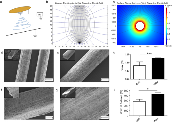
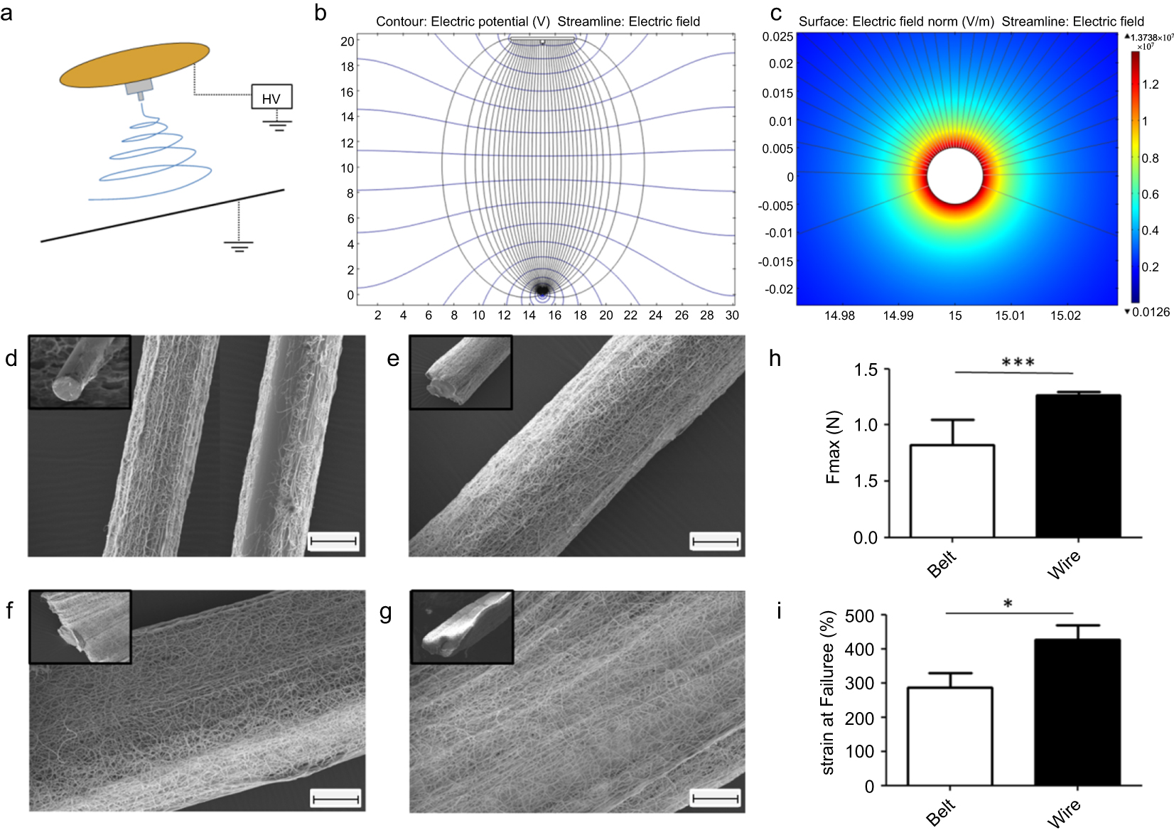
Figure 1. Collecting electrospun fibres on a thin conductive wire is efficient and creates a dense, elongated mesh which grows as a ribbon-like structure over time. (a) Sketch showing the position of the wire underneath the electrospinning nozzle. The nozzle was simplified to a brass plate with teflon tip from which the fluid is delivered. (b) A simplified 2D model in static conditions was created with COMSOL to visualize the electrical field between the nozzle and the wire-collector. The streamline and contour lines indicate that the electric field is concentric in a cross-sectional view. (c) Close-up on the wire (cross-sectional view) showing that the intensity of the electrical field increases dramatically at its surface. (d)–(g) Scanning electron microscope images of polydioxanone fibres spun onto a grounded stainless steel wire for a duration of: 5 s (d), 30 s (e), 60 s (f), 180 s (g). Images in the upper corner show the distribution of the fibre around the wire a lower magnification. (h)–(i) Compared to filaments produced with a belt collector, the use of a thin wire collector produces filaments with higher strengths and strains. Error bars represent standard deviations (n = 9). * p < 0.05; *** p < 0.001. Scale bars represent 100 μm.
Download figure:
Standard image High-resolution image2.4. Filament drawing
Detached filaments were manually stretched up to about 300% in average of their initial length. The filament was stretched between two bobbins by sections of 5 cm at an estimated rate of 5 cm s−1. The drawing of each section was stopped when resistance to deformation was felt (this was used to determine the experimental value of 300%).
2.5. Multifilament yarn assembly
Continuous multifilament yarns were assembled manually with a step size of 1 m with the help of a manual spinning device built from Lego parts (supplementary figure 2). Four filaments were twisted into a ply yarn at 400 twists/m in the right direction ('S' turn). Four of these ply yarns were then twisted together in left direction ('Z' turn) at 200 twists/m to obtain cord yarns. The number of twists corresponds to the number of full turns applied to each one meter length of yarn.
2.6. Annealing
To anneal the fibres, the bobbins of cord yarn were placed into a laboratory oven for three hours at 65 °C.
2.7. COMSOL simulation
A simplified 2D model in static conditions was created with COMSOL Multiphysics 4.3 to visualize the electrical field between the nozzle and the wire-collector in the absence of the polymer solution (no electrospinning jet). The distance between the nozzle and the collector was set at 20 cm and the voltage at 8.6 kV. The brass plate was 5 cm in diameter and the stainless steel wire was 100 μm in diameter.
2.8. In vitro degradation
In vitro degradation of yarns was carried out in a PBS solution under pH 7.4 at 37 °C in an incubator for up to 24 weeks. The cord yarns were cut to 20 mm length, weighted and sterilized for 2 h in 70% ethanol. After being washed twice in PBS, six samples were placed in 15 ml tubes containing 6 ml of Phosphate buffer saline solution (PBS) solution. A total of 12 tubes were prepared. At nine different time points (0, 2, 4, 6, 8, 10, 12, 16, 20 and 24 weeks), one tube was taken for physical characterization. At weekly intervals, the supernatant in remaining tubes was replaced with fresh PBS and its pH was measured by a pH meter (n = 12 for first time point, n = 3 for the last time point).
2.9. SEM
Samples were mounted on an aluminium stub using a carbon adhesive disk and gold coated using a SC7620 Mini Sputter Coater System (Quorum Technologies Ltd, East Sussex, UK). High resolution images were taken using an environmental scanning electron microscope (Carl Zeiss Evo LS15 Variable Pressure Scanning Electron Microscope). Three different areas were observed randomly on each sample at magnifications of ×400, ×1000 and ×2500. The diameters of fibres and filaments were measured with ImageJ (W S Rasband, US National Institutes of Health, Bethesda, Maryland, USA).
Biological samples were fixed and dehydrated prior to being mounted on the stub. Samples were fixed in glutaraldehyde (2.5% v/v in deionised water) overnight. The fixative was removed and the samples were rinsed twice in PBS before undergoing sequential dehydration in a graded ethanol series (40%, 70%, 90%, 95%, to 100% ethanol in deionised water, 10 min each step). Scaffolds were further dehydrated using hexamethyldisilazane and were left inside the fume cupboard overnight for complete drying. Samples were stored in a desiccator until use.
2.10. Tensile test
For dry tests, specimens measuring 50 mm in length were tested for failure in tension using Zwick machine at the rate of 0.5 mm min−1 until failure (n = 9). For the degradation study (n = 6), samples measuring 20 mm in length were tested in their hydrated state (soaked in PBS) after their various degradation times (see above section in vitro degradation). We assessed force at break (N), ultimate stress (MPa), Young's modulus (MPa) and breaking strain (%).
2.11. Human tendon material, donor demographics and clinical data
Tendon tissue was obtained from the Oxford Musculoskeletal Biobank, with informed donor consent in full compliance with the National and Institutional ethical requirements, the United Kingdom Human Tissue Act. Supraspinatus tendon samples were collected from patients with chronic degenerative rotator cuff tendinopathy and partial/full thickness supraspinatus tears described as small or medium in size. All patients were undergoing surgery for rotator cuff repair or subacromial decompression, during which tendon tissue was resected from the distal torn edge of the tendon and transferred immediately into a sterile tube containing DMEM F12 (Lonza, UK) for explantation. Tendon-derived cells for this study were obtained from two donors aged 53 and 58 years. Cells from each donor were used individually.
2.12. Tendon-derived cell isolation and culture
Tendon samples obtained from the two donors were cut into small uniform pieces under sterile conditions and transferred to six well plates (Corning, US) supplemented with growth medium. Growth medium used was DMEM F12 containing 50% foetal bovine serum (FBS, Biosera UK) and 1% penicillin–streptomycin solution. Plates were incubated at standard conditions (37 °C, 5% CO2) and growth medium was replaced every 2–3 days. Once cells had migrated from the explants, after approximately 7 days, the medium was refreshed with DMEM F12 containing 10% FBS. Cultures were maintained under these conditions until the wells reached confluence. The cells were then scraped and sub-cultured under the same conditions in 10 cm Petri dishes (Greiner, Germany) to allow proliferation. Tendon derived cells were used in the second or third passage for consistency and to avoid phenotypic drift.
2.13. Cell seeding on materials
Plain woven structures were created on a hand loom with the annealed yarn or monofilament PDO 4.0 (Ethicon, Johnson and Johnson Medical, Livingston, West Lothian, UK). Samples were cut to 1 cm2 in size from the woven structures and placed in 24 well plates (Corning). All materials were sterilized using 70% ethanol and dried overnight under sterile conditions at 40 °C. Tendon-derived cells were then seeded at high density (1 × 10⁵ per well) onto each well containing samples and allowed to attach for at least 12 h.
2.14. Monitoring attachment and cell growth on the materials
To assess attachment and growth on the samples, an alamarBlue (AbD Serotec, UK) assay was used. At selected time points, samples were transferred into fresh well plates containing complete medium with 5% alamarBlue. This was done in order to exclude cells attached to the polystyrene well and measure exclusively the metabolism of cells attached to the materials. After two hours of incubation, duplicates of 100 μl medium samples from each well were transferred to white 96 well plates (Corning) for analysis in the SpectraMax Gemini microplate reader (Molecular Devices, UK), with fluorescence measured at 544 nm excitation and 590 nm emission wavelength. The remaining alamarBlue medium was removed and replaced with fresh standard medium. The experiments were performed with two different patients (n = 2), each in sixplicates, and the mean values are presented in the results section.
2.15. Fluorescence microscopy
To visualize the cells using fluorescence microscopy, constructs were fixed in 10% formalin (Fisher Scientific, UK) for 5 min and permeabilized using 0.1% Triton-X (Sigma-Aldrich, UK) for 5 min. Consequently, cells were stained using rhodamine phalloidin (Invitrogen, UK) and DAPI nuclear counter stain (4',6-diamidino-2-phenylindole) according to manufacturer's instructions (Molecular Probes, UK). Samples were visualized using a fluorescence or confocal microscope (Zeiss Axio Imager M1 or a Zeiss LSM710 NLO).
2.16. In vivo study
Lewis rats were used to assess the safety of the yarns in vivo. The project licence for the study (PPL 30/2925) was approved by the local Ethical Review Committee and the UK Home Office. The infraspinatus of the rats was surgically transected 3 mm from its insertion. Tendons were repaired with two cord yarns (20 mm long) tied to each other with a single filament (stretched) and fixed to the tendon with 5-0 prolene sutures (Ethicon, Johnson & Johnson, UK). Prolene suture repair served as negative control. For positive control, vicryl patches were produced by weaving vicryl sutures (polyglactin 910, Animus Surgical, Stowmarket, UK) in 2 × 20 mm bands which were fixed to the tendon with prolene sutures. Two animals from each group (yarn, prolene and vicryl) were sacrificed at 1, 2, 4, 6, 12 and 20 weeks to examine the biocompatibility of the implants (total of animals per group: 12). Hematoxylin and eosin staining was used to assess cell infiltration and foreign-body giant cells.
2.17. Statistical analysis
Data are expressed as means with standard deviations. Graphs were created by the GraphPad Prism software version 5. Statistical analysis was performed with GraphPad Prism software. Unpaired t-test was used to examine statistical differences between two independent groups. Results were considered significant for p < 0.05.
3. Results and discussions
3.1. Collecting electrospun fibres with a wire
In this study, we propose a method which uses a thin conductive wire guide to collect electrospun fibres into filament bundles. In our experimental setup, the wire was placed underneath the electrospinning nozzle as sketched in figure 1(a). The base of the nozzle consisted of a brass plate and the charged fluid was delivered through a Teflon tip. A simplified, two-dimensional model in static conditions (in the absence of the electrospinning jet and residual charges) was created with the Comsol software to visualize the electric field between the base of the nozzle and the wire-collector. The lines of the electric field and the equipotential contours are represented in figure 1(b) (cross-sectional view). The intensity of the electric field increases dramatically in the vicinity of the wire. The electrical field also appears stronger on the top as shown by the number of incoming lines (figure 1(c)). In this work, PDO fibres were spun onto a grounded stainless steel wire (diameter: 100 μm). As shown in figures 1(d)–(g), the wire was efficient in collecting the PDO electrospun fibres. The electrospun material initially deposits on top of the wire (figure 1(d)). However, once the top of the wire is well-covered, the fibres deposit mostly sideways (figures 1(e)–(g)), causing the mesh to grow further in a ribbon-like structure rather than in a concentric manner. This may be explained by the fact that the deposited material acts as a dielectric to defect the electrical field, causing the fibre to be collected preferentially on the sides of the mesh (supplementary figure 3).
As an attempt to compare this method with previously described techniques for the production of continuous electrospun filament, we have produced filaments from a belt collector. This relates to a method developed 80 years ago by Formhals [25]. As shown in figures 1(h) and (i), the use of a thin wire produces filaments with higher strengths and strains than those produced from a flat belt collector in the form of rolled strips (for this comparison, both types of collectors were used with the same electrospinning duration and parameters to produce filaments with an equivalent amount of fibres per cross-section area). This may be due to the fact that, on the wire, fibres are directly spun as a thread, resulting in a more interconnected and therefore stronger filament than a rolled strip produced from a belt collector. Although more investigation is to be carried out to compare with other methods, similar observations may be expected with those which produce filaments from surfaces inducing less concentrated electrical fields.
3.2. Fabricating continuous filaments
To produce continuous filaments, the wire was displaced at a constant rate underneath the electrospinning nozzle and the collected fibres were detached as a non-interrupted thread. The technology is sketched in figure 2(a) and photographs of the device used in this study are presented in supplementary materials, figure 1.
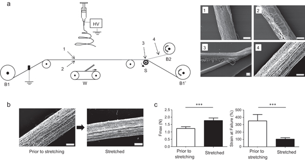
Figure 2. Method used for the fabrication of continuous electrospun filaments. (a) Sketch of the manufacturing process. The method consisted in spinning the PDO fibres on a stainless steel wire progressing at a speed of 0.6 mm s−1 underneath the electrospinning nozzle (B1: wire supply, B1': wire collection, B2: electrospun filament collection, S: cutter wheel, W: wiper). The electrospun material was then separated from the wire in the form of a continuous filament. (1)–(4) Scanning electron microscope images taken at different positions in the process. Fibres are mostly collected on the side of the wire exposed to the electrospinning jet (1) compared to the hidden side (2) The mesh can be separated from the wire (3) as one continuous thread of randomly oriented submicrofibres (4). (b) The electrospun filaments can be drawn by 300% in average of their initial length in order to align the electrospun fibres and to avoid later deformation of the material. (c) Drawing also increases the force at break significantly and reduces the strain of the material. Error bars represent standard deviations (n = 9). *** p < 0.001. Scale bars represent 100 μm.
Download figure:
Standard image High-resolution imageThe wire was stretched between two bobbins, one supplying the wire (B1) and the second re-winding it with the help of a motor (B1'). Underneath the wire, in the electrospinning jet area, a motorized wiper arm (W) was used to prevent fibres from bridging between the wire and the working surface. Scanning electron microscope images taken at different positions in the process clearly indicate that PDO fibres are mostly collected on the upper side of the wire compared to the lower side and that fibres are randomly arranged in the thread. It is worth noting that, because the wire advances at a fixed rate underneath the jet area, all points along its length eventually receive the same amount of spun material, except for its beginning and its end. This means that the thickness of the filament is consistent through its whole length, once the extremities, typically 10 to 20 cm long, have been discarded. The situation is different with typical collectors such as plates and rotating drums where samples are thicker in the centre and thinner on the sides, due to the wide angle at which the charged fluid it usually projected.
Since fibres deposit all around the circumference of the wire, opening the mesh is necessary for the detachment of the thread. This was carried out by using a rotating wheel with cutting teeth underneath the wire (S), i.e. where the density is minimal. The filament was then peeled off and wound up onto a motorized bobbin (B2). The small area of contact between the dense mesh and the wire-collector allows easy detachment and therefore the pulling force resulting from the winding was sufficient to detach the thread without breaking it. Compared to techniques using liquid collectors or solvents to detach the material from a hard surface collector, this method may therefore become advantageous for incorporating bioactive molecules or when water-soluble polymers are used. However, the performances of the device with other materials than PDO remain to be investigated. To enable a flexible design, the frame of the collection device used in this study was built from Lego parts (see method section). Although this demonstrates the simplicity and robustness of the method, the use of Lego gears limited the control over each individual wheel or spool. Fine adjustments of the tension applied to the wire were also challenging. A more advanced setup, built from machined parts and allowing precise control over each motorized wheel is currently being investigated. This will help to demonstrate the full versatility of the method in the near future. In particular, it will be crucial to determine the range of collecting speeds allowed by this technology. As demonstrated by the effect of the spinning duration (previous section), the speed of the wire influences the thickness of the filament and therefore affects its mechanical properties. In theory, collecting a single aligned electrospun fibre is possible if the speed of the wire matches the speed of the electrospinning jet (typically a few m s−1). However, this might be technically challenging due to the size and fragility of the fibre. In the textile industry, filaments must provide sufficient strengths to be able to undergo processes such as drawing, twisting and weaving without breaking.
Another important future development of the technology is to scale it up. Currently the process is relatively slow, with roughly 0.6 mm of raw material being produced per second in this work. As using multiple wires in parallel under the same nozzle would cause too many fibres to bridge between them (parallel rods are commonly used to create aligned fibres), multinozzle or nozzleless devices allowing multiple jets seem more appropriate to scale up. Preliminary results indicate that a four-nozzle setup can be used to collect a detachable filament with a wire travelling four times faster. However, further optimization work is necessary to achieve filaments with a quality similar to those obtained with a one-nozzle setup.
3.3. Filament drawing
After collection, the threads were drawn manually to prevent material deformation which could occur during further processing and applications. The drawing was stopped when the filament offered resistance to deformation, which was observed to happen at about 300% of the initial length. In addition to increasing the length of the filament, this also aligned the submicrofibres (824 ± 263 nm) in the direction of the thread, as shown in figure 2(b). This produces a structure mimetic of native fibrous tissue such as tendon and ligament. Moreover, figure 2(c) reveals that while the strain of the filament was reduced by the treatment (as expected, preventing the materials deformation during use), the force at break was significantly improved. Imparting better strength to the filaments is an effect of drawing well-known in the world of textiles but, to our knowledge, this is the first time this observation has been reported for electrospun filaments. Drawing results in further alignment of the molecular chains along the fibre axis [30] (also see supplementary materials, figure 4). This new parallel arrangement may increase weak bonding such as hydrogen bridges and van der Waal's forces, resulting in filaments with better strengths.
Compared to techniques which produce a direct twist into the filament [23, 29, 31, 32], the ability to produce relatively strong filaments with fibres aligned in the direction of the thread is more attractive in the context of scaffold design for tendon or ligament repair, since those tissues present aligned fibrous structures.
A limitation of the drawing step in this study is that it is currently performed manually and therefore still approximate. However, the consistency of drawing is reflected in the relatively small standard deviations shown in figure 2(c). Although manual stretching is still very common in the textile world, we are currently investigating the use of a bespoke drawing machine to standardize the procedure.
3.4. Assembling filaments into yarns
We then assembled the stretched filaments into a yarn using a method illustrated in figure 3(a). Photographs of the twisting setup are provided in the supplementary figure 2. First, four filaments were twisted at 400 twists/m in the right direction ('S' turn) to form 4-pied yarns (diameter: 318 ± 15 μm). Then, four of these were twisted with 200 twists/m in the left direction ('Z' turn) to form a cord yarn (F16, diameter: 929 ± 50 μm). The ratio 'S' twists/'Z' twists = 2 was selected such that the submicrofibres are aligned along the direction of the final yarn [33]. However, the 'S' and 'Z' twist numbers used in this work were chosen arbitrarily. Further work will explore the importance of this parameter on the properties of the yarn. The fact that this assembling step was performed with a hand spinning device may also represent a limitation. We are currently investigating the use of a bespoke twisting machine to standardize the procedure.
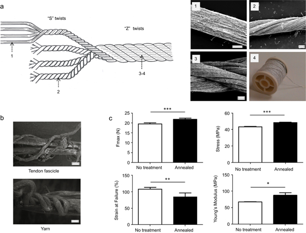
Figure 3. Assembly of the filaments into multi-filament yarns. (a) The stretched filaments (1) were assembled into 4-plied yarns by manually twisting four filaments together in a right-hand direction ('S' turn) at 400 twists/m. (2) Four of these were then twisted together in a left-hand direction ('Z' turn) at 200 twists/m to fabricate a cord yarn ((3), (4)). (b) SEM images revealing the morphological similarity between a rat tendon fascicle (top) and the yarn (bottom) after partial rupture. (c) The annealing treatment had a significant effect on the maximum force (N), maximum stress (MPa), failure strain and Young's modulus (MPa). Error bars represent standard deviations (n = 9). * p < 0.05; ** p < 0.01; *** p < 0.001. Scale bars represent 100 μm.
Download figure:
Standard image High-resolution imageInterestingly, assembling filaments into yarns may be used to mimic the hierarchical structure of native tendon fascicles, which have been shown to present a helix structure [34]. As seen in figure 3(b), morphological similarities between the yarn and a tendon fascicle are observed (seen under partial failure during tensile test). Twisting electrospun filaments into multifilament braids for soft tissue repair applications has already been reported in the literature [11, 35, 36]. However it was performed with discontinuous strands and was not demonstrated with continuous electrospun filaments. As a final post-manufacture treatment, yarns were annealed for three hours at 65 °C. This resulted in a significant increase in strength, stress and Young's modulus and a decrease in strain, as shown in figure 3(c). These changes may be due to a rearrangement of the polymer chains from a non-crystalline to a crystalline form [37]. This hypothesis is also supported by the graphs provided in supplementary materials, figure 4.
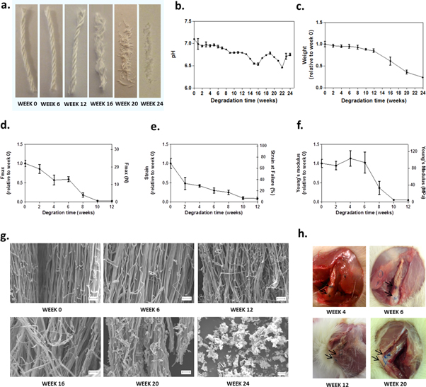
Figure 4. The multifilament yarns degrade within 6 months in vitro and in vivo. (a) Macroscopic images of dried yarns (20 mm in length) after 0, 6, 12, 16, 20 and 24 weeks of incubation in PBS solution at 37 °C. The yarns maintain their integrity up to week 12. (b) Change of the pH of the PBS solution used for in vitro degradation. (c) Change of weight of the degraded yarns relative to their initial weights (n = 6). (d) Change of force and normalized force at break. (e) Change of strain and normalized strain at break. (f) Change of Young's modulus and normalized Young's modulus (for mechanical properties: n = 6). (g) SEM images showing the submicrofibres at high magnification: breaks of the submicrofibres become evident from week 12. (h) Macroscopic images of the yarns observed during the dissection after having been implanted in rats for 4, 6, 12 and 20 weeks: no residue of the material could be found at week 20. Arrows indicate the prolene sutures. Error bars represent standard deviations. Scale bars represent 10 μm.
Download figure:
Standard image High-resolution imageOverall these results suggest that, while the number of filaments in the yarn can be adjusted to match roughly the mechanical properties of a targeted tissue, further refinements can be done by carrying out an annealing treatment. In tendons and ligaments, the ultimate tensile strength ranges between 15–100 MPa and ultimate strain % is between 10–15% for both tissues [38]. In this study, the ultimate tensile strength of the annealed yarns was 48 MPa and ultimate strain 86% on average. To a certain extent, further optimization of the annealing treatment could bring the ultimate strain to lower values, closer to those of tendons or ligaments. However, it is important to remember that PDO degrades upon implantation, resulting in rapid changes in mechanical properties. The effects of degradation on the yarn properties are presented in the following section.
3.5. Degradation properties of the material
In the context of soft tissue repair applications, PDO was selected for its known biocompatibility and its suitable degradation timeline [39]. In tendons, healing mostly occurs within the three months following injury [40]. This suggested that PDO, which degrades within 6 months [41–44], could be a good candidate material for such tissue repair. To investigate the degradation profile of the yarns, samples were incubated in PBS for up to 6 months. As shown by the macroscopic images in figure 4(a), yarns had completely lost their integrity by week 16. At a similar time point, we also observed a decrease of the incubation buffer's pH and the sample's weight (figures 4(b)–(c)). These observations are due to the low molecular weight acid degradation products that are released during the hydrolytic reaction of the polymer in the medium [41]. In vivo, these acidic compounds are known to elicit a low tissue response and to be metabolized quickly [42]. As seen in figures 4(d)–(f), mechanical properties were not measurable after week 12 due to the sample falling apart during handling. The strain at break was decreased to 48% after only two weeks of incubation. However, the maximum force was maintained for up to 59% on average after 6 weeks, thereafter rapidly decreasing to 24% at week 8. The Young's modulus was maintained at a value of around 90 MPa up to 6 weeks but fell to a value of 33 MPa at week 8 (37% of the initial modulus). SEM images (figure 4(g)) show the progressive breakage of the submicrofibres as a result of the degradation. These in vitro observations correlate well to the degradation of the material in vivo. When implanted in a rat model, yarns were still observed 12 weeks after the surgery but no evidence of the material could be found after 20 weeks (figure 4(h)). Similar observations have been reported in the literature for PDO monofilaments. PDO sutures were shown to retain about 50% of their original tensile strength after 6 weeks in vivo, 13% after 8 weeks and were absorbed in about 6 months [42–44]. The original forces at failure (i.e. prior degradation) of several PDO sutures are presented in supplementary figure 5. Compared to monofilaments, the high surface area created by the submicrofibres may contribute to an increase in the degradation rate of the yarn. Similar observations were made by Bosworth [36], who reported a degradation of polycaprolactone electrospun filaments in mice faster than expected. Further investigation is needed to determine whether the residual mechanical properties of the PDO yarns, combined to those of the newly formed tissue, are sufficient to fulfil their load-bearing functions in tendon repair applications or if the PDO yarns are better suited to be used to improve repair of tissues exposed to minimal mechanical load.
3.6. Biological performances of the yarn
Results showing the morphology, attachment and proliferation of primary human tenocytes on the yarn are shown in figure 5. PDO monofilaments, commonly used as a suture material, were used as a comparator. Cells showed no preferential direction on the monofilament while aligning themselves in the fibre direction on the nanofibrous yarns. At day 21, cells fully cover both materials (figures 5(c) and (d)). The initial cell attachment was significantly higher on the electrospun yarn compared to the monofilaments (figure 5(g)). The relatively low number of cells attached compared to the amount seeded (about 20%) may be explained by the fact that a significant area of the well was not covered with the materials (a result of both the small size of the samples and the gaps between fibres). This caused the cells to attach mostly on the bottom of the plate rather than on the fibres. Over 7 days in culture, cells proliferated on the yarns, showing a significant increase in biomass (figure 5(h)), but a significant decrease in numbers on the monofilament. Our results therefore suggest that the highly textured surface of the yarn better supported cell adhesion and growth compared to the smooth surface of monofilaments. These results are consistent with previous studies showing better attachment and growth of cells on submicrofibres mats compared to flat surfaces [45]. Nanofibrous structures are also well known to influence cell orientation [39]. More specifically, this is supported by work carried out by Barber et al [11] and Bosworth et al [12, 36, 46], who demonstrated that twisted electrospun filaments promote cell attachment, induce cytoskeletal reorganization and promote cell alignment for the regeneration of anisotropic tissues. However, the present study is limited by the number of repeats and by the extent of the work. Further characterization in vitro will be carried out to understand in depth the cell-material interactions.
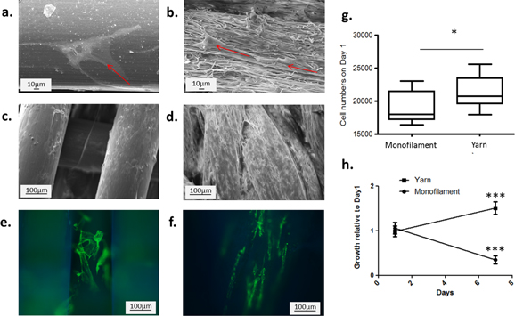
Figure 5. In vitro comparison of electrospun yarns and monofilament fibres, using a primary human tenocytes model. (a)–(d) SEM images showing cell morphology and spreading (red arrows) 24 h after seeding on PDO monofilament (a) and yarns (b) and 21 days after seeding on PDO monofilament (c) and yarns (d). (e)–(f) Fluorescence images showing cell orientation 3 days after seeding on PDO monofilament (e) and yarns (f). (g) Numbers of cells attached to the material 24 h after seeding. (h) Relative cell growth on the materials over 7 days. Error bars represent standard deviations (n = 2, each in sixplicates). *** p < 0.001.
Download figure:
Standard image High-resolution image3.7. Safety of the material in vivo
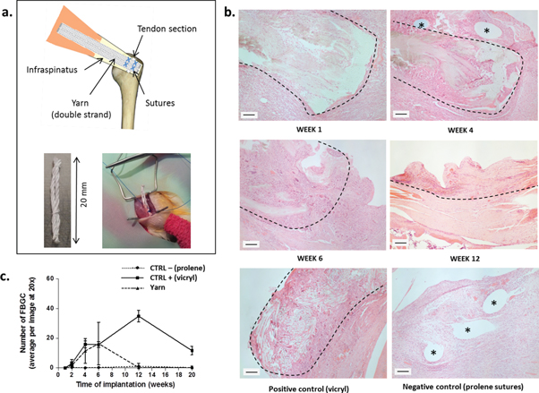
The safety of the electrospun yarn was characterized in vivo using a rat model (figure 6). Yarns were implanted directly above transected infraspinatus tendons for periods of 1, 2, 4, 6, 12 and 20 weeks, as shown in figure 6(a). Non-degradable prolene suture repair was used as negative control and vicryl suture patches as positive control (vicryl is known to cause a significant foreign body reaction). Histological sections were used to demonstrate the extent of cell infiltration and foreign body response. Interestingly, cells infiltrated the material well over the implantation time, as depicted in figure 6(b). Similar observations were made by Bosworth [36], after implanting PCL electrospun filaments in mice. As underlined by the authors, cell infiltration into the yarn is crucial for the long-term success of the implant, whereas a simple encapsulation could lead to failure as the material degrades. Foreign body giant cells (FBGC) were counted from histological sections and results are reported in figure 6(c). The number of FBGC on yarn samples increased at week 6 to a level equivalent to the positive control but returned to levels comparable to the negative control afterwards. Additional images of histological sections for yarn samples and controls are provided in supplementary figures 6–8. Although FBGC counts were not reported by Bosworth and collaborators during their in vivo study, the presence of FBGC around non-woven electrospun meshes has been described in the literature and was suggested to be induced by the high surface-to-volume ratio of the yarn and its degradation products [47, 48]. The presence of FBGCs is not surprising since it is a natural response to the presence of implants and in particular to degrading ones. However, minimizing the presence of FBGCs is important in the development of materials with improved biocompatibilities. The fact that electrospun PDO yarns cause a milder reaction compared to the widely-used vicryl sutures (used here as positive control) is therefore encouraging as it suggests that electrospun yarns are more biocompatible.
Figure 6. Safety evaluation of the electrospun yarns carried out in a rat model. (a) The infraspinatus of the rats was surgically transected 3 mm from its insertion. Tendons were repaired with two cord yarns (20 mm long) tied to each other with a single filament and fixed to the tendon with 5-0 prolene sutures. Vicryl patches and prolene suture repair served as positive and negative controls. (b) Hematoxylin and eosin staining of section of the repair area after 1, 4, 6 and 12 weeks. Positive and negative controls are shown at week 4. Interrupted lines indicate areas in the tissue section where the material was identified. Asterisks: prolene suture holes. (c) Graph representing the average number of foreign body giant cells (FBGC) per image (20x) for each time point and each material. Error bars represent standard deviations (values were obtained from 20 images). Scale bars represent 100 μm.
Download figure:
Standard image High-resolution image
This early in vivo data is presented to demonstrate that PDO electrospun yarns are safe for implantation. This was expected since PDO is a FDA-approved, widely used suture material. Further work may be needed to confirm the absence of organic solvent traces into the yarn. However, the treatments applied (which include vacuum, heating and washes in both ethanol and PBS) are likely to remove all solvent traces from the electrospun material [49].
It is interesting to note that the multifilament and submicrofibrous nature of electrospun yarn may be favourable to encourage better quality healing through infiltration of cells, compared to a closed, solid monofilament material. However, we have not addressed the question of efficacy of the repair in this paper, principally because no good animal models of degenerate human tendon and ligament disease exists. New models, which are currently being developed, will be used in the future to evaluate the quality of the new formed tissue and the efficacy of the repair using electrospun yarns.
4. Conclusions
We report a method that fabricates continuous submicrofibrous filaments. We demonstrate that using a wire as a collector is an efficient method to concentrate the electrical field and assemble fibres as a dense, elongated mesh. This mesh can be detached into a filament without using a liquid such as ethanol to separate it from the wire. This offers a clear advantage particularly when incorporating bioactive molecules or when water-soluble polymers are used. The technology is simple, scalable and the use of motorized wheels offers control over filament formation, detachment and collection. We also show that treatments such as drawing (stretching), twisting and annealing are useful to improve the filament and yarn performances, and may be used to enhance the biomimetic qualities of the material and its mechanical properties. These treatments are common in yarn textile manufacturing, suggesting the possibility of integrating the technology into existing textile production lines. Many aspects of the method, however, remain to be investigated. This includes exploring the spinning of other polymers with different characteristics, investigating the effect of adding bioactive molecules, determining the influence of production rate on filament quality, testing the setup in combination with multinozzle or nozzleless devices for scaled up productions, etc. This method has important implications for the field of medical textiles as it may lead to improvements of current surgical sutures, wound dressings, and implantable devices. In particular, it may contribute to the development of medical fibres and textiles which aim to stimulate the endogenous repair of soft tissues to improve tissue healing and help to accelerate patient rehabilitation. To illustrate the potential benefit of electrospun yarns as medical textiles, we have carried out in vitro and in vivo studies, narrowing the applications of electrospun yarns to tendon repair. Our findings suggest that electrospun yarns have the ability to improve cell shape, attachment and proliferation compared to current monofilaments and that they are safe for implantation. However, further investigation is required to understand cell-material interactions, to evaluate the efficacy of the repair using these electrospun yarns and to determine the real benefit to patient.
To summarize, this method for the fabrication of continuous electrospun filaments is promising because of its simplicity, its robustness and its ability to be scaled up and incorporated into existing textile production lines. Further work should determine its real potential as a platform for the fabrication of future medical textiles with improved healing properties.
Acknowledgments
The authors gratefully acknowledge financial support from the National Institute for Health Research. The authors acknowledge the assistance of Dr Sarah Franklin with the in vivo experiments, Dr Kalin Dragnevski with electron microscopy and Mr Nickolas Hawkins with the DSC scans.
Author disclosure statement
The authors declare no competing financial interests.