

Abstract
The present study describes the fabrication of polyaniline-silk fibroin (PASF) nanocomposite-based nerve conduits and their subsequent implantation in a rat sciatic nerve injury model for peripheral nerve regeneration. This is the first in vivo study of polyaniline-based nerve conduits describing the safety and efficacy of the conduits in treating peripheral nerve injuries. The nanocomposite was synthesized by electrospinning a mixture of silk fibroin protein and polyaniline wherein the silk nanofibers were observed to be uniformly coated with polyaniline nanoparticles. Tubular shaped nerve conduits were subsequently formed by multiple rolling of the electrospun sheet over a stainless steel mandrel. The conduits were characterized in vitro for their physico-chemical properties as well as their compatibility with rat Schwann cells. Upon implantation in a 10 mm sciatic nerve injury model, the conduits were evaluated for their neuro-regenerative potential through extensive electrophysiological studies and monitoring of gait pattern over a course of 12 months. Gross examination, histological and ultra-structure analyses of the conduits and the regenerated nerve were also performed to evaluate morphological regeneration of transected nerve. PASF nanocomposite conduits seeded with Schwann cell (cell seeded PASF) exhibited excellent nerve conduction velocity (NCV) (50 m s−1), compound muscle action potential (CMAP) (12.8 mV), motor unit potential (MUP) (124 μV), growth of healthy tissue along the nerve gap and thick myelination of axons 12 months after implantation indicating enhanced neuro-regeneration. The excellent functional recovery achieved by animals implanted with cell seeded PASF conduits (86.2% NCV; 80.00% CMAP; 76.07% MUP) are superior to outcomes achieved previously with similar electrically conductive conduits. We believe that the present study would encourage further research in developing electrically active neural implants using synthetic conducting polymers and the in vivo applications of the same.
Export citation and abstract BibTeX RIS
1. Introduction
Polyaniline is one of the most common intrinsically conducting polymers explored for multidisciplinary applications. The superior thermal stability, easy processing into various forms (solutions or micro/nanostructure) using an inexpensive monomer (aniline) are some of the properties which make polyaniline an attractive choice as a scaffold material [1–3]. Polyaniline-based films or powders have been found to support cellular adhesion and proliferation and did not elicit any toxic or immune response upon subcutaneous implantation in rats over a period of 50 weeks, thereby proving its biocompatibility [4]. Further, the ability of polyaniline-based scaffolds to support the growth of neuronal cells, differentiation of neural stem cells and promote neurite extension upon external electrical stimulation indicates its potential in fabricating artificial nerve conduits for neural tissue engineering applications [5, 6]. The present study is the first report of fabricating polyaniline-based artificial nerve conduits and evaluating their efficacy in promoting functional and morphological regeneration of nerves.
Peripheral nerve damage following trauma or other neuropathic manifestations often lead to permanent disability through loss of sensory and motor function. Artificial nerve conduits fabricated using biocompatible synthetic and natural polymers are essential to bridge nerve gaps larger than 5 mm and augment nerve regeneration by guiding the sprouting axons from the proximal and distal stumps [7]. However, to address the loss of nerve impulse transmission following nerve injury it is imperative that the artificial nerve grafts favor electrical conduction. Conductive polymers like polypyrrole, carbon nanofiber etc have been used as dopants to fabricate scaffolds and develop artificial nerve guides [8, 9]. Although electrically conductive polymers have been reported to favor growth and functional regeneration of nerve cells and tissue, the exact mechanism behind such neuro-regenerative effects is yet to be fully understood [10, 11]. Further, very little is known about the biodegradability and chronic in situ toxic effects of degradation by-products of synthetic conducting polymers due to limited in vivo studies as neural implants.
Among the natural polymers, silk fibroin- and silk-based composites have been extensively used in neural tissue engineering due to their excellent biological and mechanical properties, tunable architecture, high permeability to body fluids and controlled degradation in vivo. However, the poor electrical conductivity of the silk polymer has to be improved in order to achieve better results in regeneration of electrically active tissues like cardiac muscles and nerve fibers. Our group has recently reported that incorporating metallic nanoparticles into silk nanofibers can considerably decrease the resistance of silk and augment near-normal functional and morphological regeneration of a transected sciatic nerve [12]. Intrinsically conducting polymers like poly-3,4-ethylenedioxythiophene (PEDOT), polypyrrole, polyaniline etc have a conjugated π-electron system, low ionization potential and high electron affinity, which are responsible for their electrical conductivity through electron delocalization. Silk-based scaffolds doped with such conducting polymers have been reported to increase the electrical conductivity of the material thereby facilitating transmittance of the action potential and nerve regeneration. Silk nanofiber-based meshes coated with polypyrrole were found to be compatible with human mesenchymal stem cells and human fibroblast cells [13]. Electrospun core–sheath nanofibrous meshes comprising polyaniline-silk fibroin (PASF)-poly(L-lactic acid-co-3-caprolactone) have been reported to promote the growth and differentiation of the rat PC12 cell line [14]. Silk threads have also been combined with the conductive polymer poly(3,4-ethylenedioxythiophene)-poly(styrenesulfonate) (PEDOT-PSS) in order to develop biocompatible electrodes to record signals during electrophysiological tests such as electrocardiography, electroencephalography and evoked potential data [15]. In vivo studies with silk fibroin–single walled carbon nanotube-based porous nerve conduits along with intraluminal fillers of fibronectin nanofibers exhibited a higher number of myelinated axons and higher nerve conduction velocities upon implantation on a rat sciatic nerve injury model [16]. These studies indicate that the efficacy of silk fibroin as a biomaterial for facilitating nerve regeneration can be increased by incorporation of electrical cues in the nerve conduits upon combination with synthetic conducting polymers.
In the present study we have fabricated nerve conduits based on a PASF nanocomposite. The nerve conduits were tested for their biocompatibility in vitro and in vivo, seeded with rat Schwann cell line SCTM41 cells and implanted in a 10 mm sciatic nerve gap. The electrophysiological and histomorphometric outcomes of the nanocomposite group was compared with those of animals with pure silk fibroin nanofiber-based conduits as well as with the untreated control group over a period of 12 months in order to understand the long term safety of such synthetic polymers as well as their effect on nerve regeneration in vivo.
2. Materials and methods
2.1. Synthesis of polyaniline and its cytotoxicity studies
Polyaniline (PA) was synthesized from aniline monomers upon polymerization following a previously described procedure [17, 18]. Briefly, 1 ml of aniline monomer was added to 20 ml 0.1 M HCl solution at room temperature and stirred for 15 min. Thereafter 2.49 g of ammonium persulfate (APS) in 10 ml of 0.1 M HCl solution was added to the above solution in one portion. The mixture solution was allowed to polymerize without stirring at room temperature for 24 h. After filtering the resulting product was washed with deionised water and methanol. There after it was dried under vacuum at 60 °C for 24 h to obtain a green amorphous powder.
The rat Schwann cell line (SCTM41) generated from post-natal sciatic nerve cultures of CD rats (Charles River Lab, Margate, UK) was used as the cell source for the study [19]. The cytotoxic effect of the polyaniline (PA) was assessed by MTT assay on a rat following standard assay procedures [20]. Briefly, PA were dispersed in Dulbecco's modified eagle's medium (DMEM) without serum to make a stock solution of 10 mg ml−1. This solution was used to make further working concentrations (100–1000 μg ml−1) of PA against which the MTT assay was done. The cells were cultured in 96 well cell culture plates at a density of 1 × 10⁴ cells per well and incubated with various amounts of PA (10–100 μg) dissolved in 100 μl of serum free DMEM for 24 h in a CO2 incubator (Make-Healforce) under 37 °C and relative humidity of 90%. This was followed by addition of DMSO and recording absorbance at 570 nm using a UV–vis multiwell plate reader (Make-TECAN). In the control group cells were left untreated and only 100 μl of serum free DMEM was added. The cell viability was expressed as a percentage of the control by the following equation:

where Nt is the absorbance of the cells treated with PA and Nc is the absorbance of the untreated cells. Cells treated with 5% dimethyl sulfoxide (DMSO) in serum free DMEM for 24 h were considered as positive control. A live–dead staining assay was performed using acriding an orange (AO)–ethidium bromide (EB) mixture. For the AO–EB staining assay, the Schwann cells after 24 h incubation with PA (100 and 1000 μg ml−1) were treated with 20 μl of the AO–EB mixture dye solution. After a 2–3 min incubation period, both samples were observed under an inverted fluorescent microscope [21]. The same procedure was followed with untreated Schwann cells as a negative control and cells treated with 5% DMSO for 24 h as a positive control.
2.2. Molecular mass characterization of synthesized polyaniline
Matrix-assisted laser desorption/ionization (MALDI) was used to characterize the molecular mass of synthesized polyaniline. MALDI was performed separately on polyaniline samples dissolved in tetrahydrofuran (THF) and acetonitrile. Solventless MALDI was also performed by mixing the sample directly with the MALDI matrix. The samples were prepared following the standard procedure reported earlier [22].
2.2.1. Sample preparation for solvent-based MALDI
Two different solvents were used i.e. acetonitrile and THF. 5 mg of polyaniline was dissolved in both acetonitrile and THF separately. After 10 min, the samples were centrifuged and the solid polyaniline that had not dissolved was decanted off. For the preparation of matrix, 0.1% of trifluoroacetic acid solution in distilled water was mixed with acetonitrile in the ratio of 60:40 respectively. 15 mg of 2,5-dihydroxybenzoic acid (DHB) matrix was added to 1 ml of the prepared solution. This was further sonicated in a water bath sonicator for 5 min. This matrix solution and polyaniline containing sample solution were mixed in a 1:1 ratio. The samples were then spotted onto the sample plate and allowed to air dry.
2.2.2. Sample preparation for solventless MALDI
For solventless MALDI, the DHB matrix was prepared as mentioned above. Polyaniline powder was then mixed and ground with the DHB matrix using a mortar-pestle in a sample:matrix ratio of 1:50. The sample was then spotted onto the sample plate and allowed to air dry.
All analyses were performed in the MALDI-TOF mass spectrometer (Make-Bruker) equipped with a nitrogen laser (wavelength = 333 nm). The analyzer was operated in the reflectron mode with the mass range of 500–1500 m/z. All spectra were generated with an acceleration voltage of 19 kV and with average of 500 laser shots. Data acquisition and analysis were done using the Bruker Flex Control program. Representative structures of polyaniline were drawn using ChemDraw Ultra 12 software.
2.3. Fabrication and characterization of an electrospun SF and PASF nanofibrous mat
Bombyx mori silk cocoons were purchased from a local market in Guwahati, Assam and degummed as per the standard protocol reported earlier [23]. Briefly, B. mori silk cocoons were boiled for 30 min in distilled water. Thereafter cocoons were rinsed and immersed in an aqueous solution of 0.2% sodium carbonate and 0.025% detergent (like Triton X-100) and kept at 90 °C for 3 h to completely remove sericin protein. The degummed silk fibroin fibers were left to dry at 60 °C overnight after rinsing thoroughly with distilled water. The degummed silk fibers were then dissolved in a highly concentrated chaotropic solvent (9 M lithium bromide) in a material:liquor ratio of 1:10. The procedure was carried out under magnetic stirring conditions and a temperature of 60 °C until all the fibers dissolved. Subsequently, the solution was dialyzed against distilled water (MW cut off—8000) for 3–4 d with frequent changes of water. The aqueous solution of pristine silk fibroin thus obtained was concentrated by further dialysis against polyethylene glycol (MW = 20 000) until the concentration of the protein solution reached about 15%. The protein solution was stored at −20 °C overnight followed by freeze drying for 2–3 d.
The lyophilized powder of pristine silk fibroin protein (SF) was dissolved in formic acid (98% pure) at a concentration of 10% w/v (i.e. 100 mg ml−1) for electrospinning. Polyaniline powder was also added into the formic acid in a polyaniline:silk ratio of 1:100 and left under constant stirring overnight. The spinning solution was taken in a 2 ml syringe and electrospun under optimized conditions where the operating voltage ranged from 20 to 25 kV, working distance (i.e. distance between needle tip and collector) of 15 cm and flow rate of 0.5–1 ml hr−1 and the nanofibers were collected on a rotating drum covered with an aluminum sheet.
The PASF, pristine silk fibroin (SF) electrospun mats as well as PA powder were dried overnight and scraped before x-ray diffraction (XRD) and Fourier transform infrared (FTIR) spectroscopic studies. In order to study the electrical resistance, a 1 cm × 1 cm portion of the electrospun mats (SF and PASF) was placed over the uncoated portion of a aluminum coated corning glass with the edges of the mat fixed on the aluminum coated section using silver paste. The electrical resistance of the materials was measured by a sub-femto-ampmeter (Make-Keithley). The thermal properties of the scaffolds (PASF and SF) as well as the PA powder were analyzed by TGA (make: Netzsch). The temperature range for the analysis was set from 30 °C to 800 °C.
Pristine SF and PASF nanofibers were collected in cover slip separately for culture of cells. Nanofiber-coated cover slips were treated with methanol and exposed to UV radiation for 10 min to induce β sheet conversion and sterilization. They were then washed 3–4 times with sterile phosphate buffer saline (PBS) and incubated with DMEM containing 10% FBS for 24 h in CO2 incubator for conditioning. SCTM 41 cells (rat Schwann cells) were seeded over cover slips and incubated for 10 d with regular replacement of media. On the fifth day the samples were fixed with 4% paraformaldehyde prior to FESEM analysis to monitor cell adhesion. Cellular proliferation was also quantitatively studied over the cover slips by MTT analysis on the 0, 5th and 10th day.
2.4. Fabrication and characterization of cell-seeded and un-seeded nerve conduits
The electrospun nanofibrous mat (made either of PASF or SF) was rolled multiple times to form a conduit and further processed for sterility and cell culture as described in our earlier study [12]. For cell seeded conduits, 1 × 10⁵ SCTM41 cells (rat Schwann cells) resuspended in complete DMEM were seeded inside the conduits and cultured for 5 d in vitro with a daily change of media. Before implantation the conduits were gently washed 3–4 times with sterile PBS.
The porosity and swelling ratio of the conduits (n = 4) were determined following previously reported methods [24].
2.5. In vivo intracutaneous toxicity study
Intracutaneous irritation and toxicity studies were performed on Sprague Dawley rats (n = 9) following ASTM standards as described earlier [24]. SF (n = 3) and PASF nerve conduit (n = 3) were immersed in normal saline for 24 h and the extract was injected intradermally. The control group (n = 3) received only saline injections.
2.6. Surgical implantation of nerve conduits
All the animal experimentations were performed under veterinary supervision following CPCSEA, India and Institutional Animal Ethical Committee (IAEC) guidelines at College of Veterinary Sciences, AAU, Khanapara, Assam. The study was approved by IAEC and CPCSEA vide approval no 770/ac/CPCSEA/FVSc/AAU/IAEC/11-12/117 dated 27.03.2012. The animals were housed in a temperature and humidity controlled room with access to food and water ad libitum.
The fabricated nerve conduits were subsequently implanted in clinically healthy female Sprague Dawley rats (aged 3 months and weighing 250 g). A total of 40 rats were taken for the study. The animals were divided into five groups, each comprising of 8 animals and a gap of 10 mm was created in the sciatic nerve. Group I was treated with silk fibroin (SF) nanofiber nerve conduit (n = 8), Group II consisted of Schwann cell seeded SF conduits (n = 8), Group III were implanted with PASF nanocomposite nerve conduit (n = 8) and Group IV were treated with Schwann cell seeded PASF conduits. Group V was the negative control group where the sciatic nerve gap was left untreated (n = 8). The surgical procedure followed is described in figures 9(B)–(D). The operation was done under balanced anesthesia using a combination of xylazine (5 mg kg−1 body weight) and ketamine (50–100 mg kg−1 body weight) intra-peritoneally. The right sciatic nerve was surgically exposed and subsequently separated from the underlying muscles and fascia. A 10 mm long nerve segment of the sciatic nerve was transacted and removed. The proximal and distal stumps of the nerve were slowly inserted inside the conduit and sutured along with the conduit using 7–0 polypropylene sutures. Subsequently, the muscles and skin were sutured using 7–0 polypropylene and 6–0 black braided silk sutures respectively and sealed with a tincture of benzoin cotton seal. Animals were then maintained on antibiotic (ceftriaxone) and non-steroidal anti-inflammatory drug (Meloxicam) for 5 d postoperatively. Regular dressing was done with a 5% povidine iodine solution (Betadine) and antiseptic solution spray for 7 d. Skin sutures were removed after 8–10 d.
2.7. Functional analysis of regenerated sciatic nerves
Functional regeneration was assessed by electrophysiological and walking track analysis using similar methods as reported in our previous study [12]. The electrophysiological study comprised recording nerve conduction velocity (NCV), compound muscle action potential (CMAP) along with motor unit potentials (MUPs), whereas walking track analysis involved calculating the sciatic function index (SFI) from the gait pattern of animals per the following formula [25]
where, EPL—experimental print length; NPL—normal print length; ETS—experimental toe spread; NTS—normal toe spread; EITS—experimental inter toe spread; NITS—normal inter toe spread.
2.8. Morphological analysis of regenerated sciatic nerves
The animals with conduits were euthanized by over dose of thiopentone sodium (i.v.) 6 and 12 months after surgery. The graft region along with the conduit was harvested and processed for histology as described in our earlier study [12]. The animals in the control group (no conduit implanted) were sacrificed after 12 months and the site of the operation was cut open to observe tissue regeneration across the nerve gap. Cross-sections of the graft region harvested after 12 months were stained with osmium tetra-oxide to be visualized by transmission electron microscopy (TEM) for monitoring internal tissue architecture.
3. Results
3.1. Synthesis and cytotoxicity of polyaniline
The polyaniline amorphous powder formed after subsequent polymerization was dark green in color with a fluffy texture. Scanning electron microscope observation of the powder showed the presence of aggregates (figure 1(A)). Rat Schwann cells (SCTM41) exhibited high cellular viability (80%) by MTT assay when treated with maximum concentration of polyaniline i.e. 1000 μg ml−1. The positive control group treated with 5% DMSO exhibited very low cell viability of 19% (figure 1(B)). The live–dead assay of SCTM41 cells treated with 1000 μg ml−1 PA revealed normal cellular morphology compared to the negative control untreated cells (figures 1(C)–(H)). The positive control group treated with 5% DMSO showed damaged cell architecture with rounded cells (figures 1(I)–(K)).

Figure 1. Fabrication and cytotoxicity of polyaniline powder. (A) Scanning electron microscope (SEM) image of polyaniline (PA) powder, (B) viability of rat Schwann cells (SCTM41) treated with PA measured by MTT assay compared to the 5% DMSO treated group. (C)–(E) Live–dead staining assay of untreated SCTM41 cells under normal light (C), green fluorescence (AO stained) (D) and red fluorescence (EB stained) (E). (F)–(H) Live–dead staining assay of SCTM41 cells treated with 1000 μg ml−1 under normal light (F), green fluorescence (AO stained) (G) and red fluorescence (EB stained) (H). (I)–(K) Live–dead staining assay of SCTM41 cells treated with 5% DMSO under normal light (F), green fluorescence (AO stained) (G) and red fluorescence (EB stained).
Download figure:
Standard image High-resolution image3.2. Molecular mass characterization of the synthesized polyaniline
Solvent-based MALDI with polyaniline dissolved in acetonitrile showed prominent peaks at m/z = 542, 558, 574, 634, 650, 666 and low intensity peaks corresponding to m/z = 725 and 741. Similar peaks were found using THF as a solvent with one extra peak at m/z = 757 (figures 2(A), (B)).
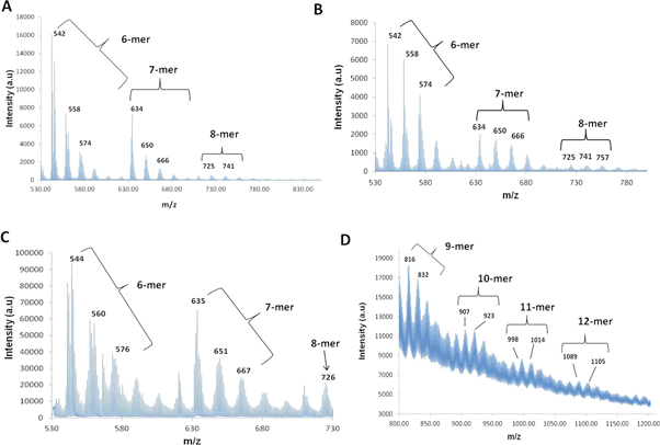
Figure 2. Molecular mass distribution of synthesized polyaniline (PA). (A) PA in acetonitrile; (B) PA in THF; (C)–(D) solventless MALDI showing low molecular weight oligomers (C) and higher molecular weight oligomers of PA (D).
Download figure:
Standard image High-resolution imageSolventless MALDI was performed over the m/z range 530–730 and 800–1200. Prominent peaks were found at m/z = 544, 560, 576, 635, 651, 667 and 726 (figure 2(C)). In the higher m/z range sharp peaks were observed at m/z = 816, 832, 907, 923, 998, 1014, 1089 and 1105 (figure 2(D)). The possible chemical structures of the aniline oligomers were derived by analyzing the spectra from solvent-based as well as solventless MALDI (figure 3).

Figure 3. Representative structures of different types of aniline oligomers. (i) Aniline oligomers terminated by a phenyl group at both ends (lowest molecular weight species), (ii) oligomers having an amine at one terminal and an equal number of six-carbon rings and nitrogen atoms, (iii) oligomers having an amine group at both terminals.
Download figure:
Standard image High-resolution image3.3. Fabrication and characterization of electrospun SF and PASF nanofibrous mats
The morphology of the electrospun mats (SF and PASF) were observed under an electron microscope. FESEM analysis revealed the formation of a nanofibrous mesh in both SF and PASF scaffolds with an average fiber diameter of 150–250 nm in case of SF and 350–450 nm for the electrospun PASF mat (figures 4(A), (B), (D)). PASF nanofibers were found to be coated with numerous nanosized particles with an average particle diameter of 40–60 nm (figure 4(C)). Rat Schwann cells (SCTM41) were observed to adhere over both electrospun mats (SF and PASF) (figures 4(E), (F)). MTT assay of cells cultured over the scaffolds for 10 d indicated enhanced cellular proliferation in the case of nanofibrous mats as compared to a control 12 well plate (figure 4(G)).

Figure 4. Fabrication of electrospun scaffolds and cellular proliferation. (A) FESEM image of silk fibroin (SF) nanofibers with a SF sheet in the inset, (B) FESEM image of polyaniline–silk fibroin (PASF) composite nanofibers with a PASF sheet in the inset, (C) higher magnification of FESEM image of PASF nanofibers showing uniform coating with polyaniline nanoparticles. The particle size distribution is depicted in the inset, (D) variation of fiber diameter in SF and PASF nanofibrous scaffolds, (E) FESEM image of Schwann cell growth on the SF scaffold and (F) FESEM image of Schwann cell growth on the PASF scaffold, (G) cellular proliferation over electrospun scaffolds and a 12 well cell culture plate (control) measured by MTT assay.
Download figure:
Standard image High-resolution imageThe electrical resistance of the SF nanofiber mat was found to be 12.39 × 10¹² Ω whereas PASF nanofibers had a resistance of 1 × 10¹² Ω.
FTIR analysis of the SF electrospun mat exhibited peaks around 1668, 1514, 1240 and 1146 cm−1. PA powder was also found to have peaks identical to SF with a few additional peaks corresponding to 931, 777, 725, 644, 517 cm−1. PASF nanocomposite scaffolds were found to exhibit peaks around 1614, 1541, 1257, 1119 and 663 cm−1 (figure 5(A)).
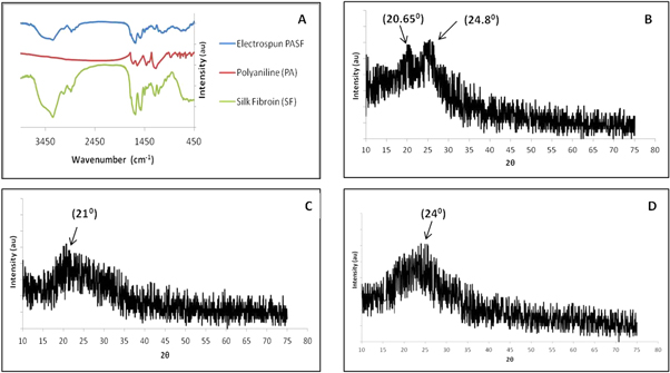
Figure 5. Characterization of electrospun scaffolds. (A) FTIR spectrum of PA, PASF and SF scaffolds, (B)–(D) XRD spectrum of (B) PASF nanocomposite, (C) SF nanofibers and (D) PA powder samples.
Download figure:
Standard image High-resolution imagePA powder exhibited a single broad peak at 2θ = 24° in XRD analysis while the SF electrospun mat had a broad peak around 2θ = 21° (figures 5(C), (D)). The electrospun PASF nanocomposite mat showed a broad peak around 2θ = 20.65° and a minor peak around 2θ = 24.8° (figure 5(B)).
Thermogravimetric analysis of PA showed a major weight loss around 205 °C while SF and PASF exhibited a similar weight loss around 244.7 °C and 245.9 °C respectively (figure 6).

Figure 6. Thermo-gravimetric analysis of scaffolds. Thermal curves of polyaniline (PA), composite (PASF) nanofibers and silk fibroin (SF) nanofibers.
Download figure:
Standard image High-resolution image3.4. Fabrication and characterization of cell seeded and un-seeded nerve conduits
The fabricated nerve conduits had an internal diameter of around 1.3 mm and wall thickness of 0.5 mm comprising multiple layers organized in a layer-by-layer fashion (figures 7(A)–(D)). Rat Schwann cells (SCTM41) were also found to adhere and proliferate on both PASF and SF conduits (figures 7(E), (F)). The porosity of the SF and PASF nerve conduits was observed to be 15.8% (±0.2) and 11.2% (±0.3) respectively. The SF conduits exhibited a maximum swelling ratio of 33.5% whereas the PASF conduits were found to have a swelling ratio of 15.3% after 24 h (figure 8).
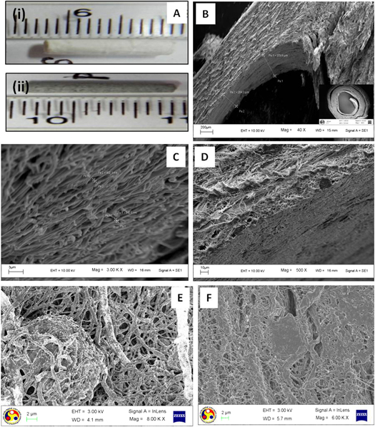
Figure 7. Morphology of nerve conduit and cellular growth on conduits. (A) Digital image of silk fibroin (i) and silk fibroin–polyaniline nerve conduit (ii). (B)–(D) FESEM images of a nerve conduit illustrating the stacking of multiple layers of nanofibers, the inset shows the cross section of a conduit, (E) Schwann cell adhesion and proliferation on a PASF nerve conduit, (F) Schwann cell adhesion and proliferation on a SF nerve conduit.
Download figure:
Standard image High-resolution image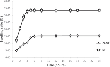
Figure 8. Dynamic swelling ratio of PASF and SF conduits over 24 h.
Download figure:
Standard image High-resolution image3.5. In vivo intracutaneous toxicity study
The saline extract of both the conduits (PASF and SF) did not induce formation of erythema or edema in the in vivo intracutaneous irritation test (figure 9(A)).
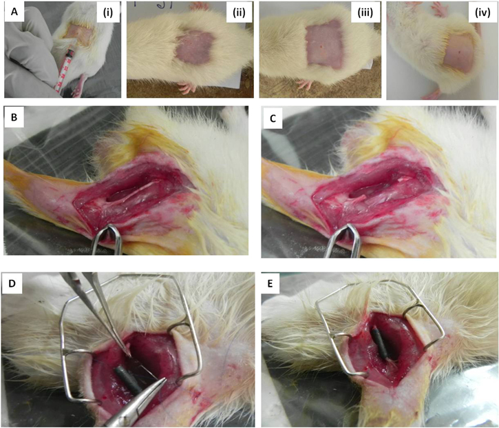
Figure 9. Intracutaneous skin irritation test and surgical implantation of conduit. (A) (i) Intracutaneuous skin irritation test by administration of compounds through intradermal injection, nature of skin 72 h after administration of (ii) saline extract of PASF conduits, (iii) saline extract of SF conduits and (iv) normal saline. (B)–(E) The surgical procedure followed for implantation of the conduit.
Download figure:
Standard image High-resolution image3.6. Surgical implantation of nerve conduits
The dimensions, strength and texture of the nerve conduits were found to be appropriate for implantation in a rat sciatic nerve injury model and was observed to maintain its integrity during and after surgery (figures 9(D), (E)).
3.7. Functional analysis of regenerated sciatic nerves
Electrophysiological tests and SFI were used to evaluate functional neuro-regeneration 6 and 12 months post implantation of conduits.
The wave patterns of CMAP obtained from both SF and PASF nanocomposite groups following stimulation near the proximal and distal ends of the implanted conduits are shown in figure 10.
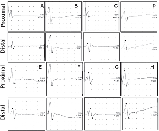
Figure 10. Wave pattern of compound muscle action potential. Action potential recorded after stimulating at the proximal and distal ends of an implanted conduit (A) PASF group after 6 months, (B) PASF group after 12 months, (C) SF group after 6 months, (D) SF group after 12 months, (E) cell seeded PASF conduits after 6 months, (F) cell seeded PASF conduits after 12 months, (G) cell seeded SF conduits after 6 months and (H) cell seeded SF conduits after 12 months.
Download figure:
Standard image High-resolution imageThe electrophysiological parameters for evaluating the extent of functional regeneration as well as the percentage of recovery compared to a normal rat are given in table 1. A normal nerve was found to exhibit an average CMAP of 16 mV upon quantitative analysis of the peak amplitude obtained from action potential signals. In comparison, the PASF nanocomposite group exhibited CMAP of 4.8 mV and 12 mV after 6 months and 12 months of implantation respectively. The animals treated with cell seeded nanocomposite conduits (PASF-cell) were found to have CMAP of 5.7 mV and 12.8 mV after 6 months and 12 months of implantation respectively. Animals with SF conduits had an average CMAP of 3.4 mV and 5.5 mV after 6 and 12 months of conduit implantation respectively. Schwann cell seeded SF conduits were found to exhibit CMAP of 4.2 mV and 11 mV after 6 and 12 months post surgery respectively.
Table 1. Electrophysiological parameters obtained in different groups.
| Nerve conduction velocity (m s−1) | Compound muscle action potential (mV) | Motor unit potential (μV) | ||||
|---|---|---|---|---|---|---|
| GROUPS | Recorded value | Percentage recovery relative to normal | Recorded value | Percentage recovery relative to normal | Recorded value | Percentage recovery relative to normal |
| NORMAL | 58 ± 2 | 100% | 16 ± 1.5 | 100% | 163 ± 3.6 | 100% |
| PASF-6 months | 40 ± 2.2 | 68.96% | 4.8 ± 1.2 | 30% | 112 ± 2.9 | 68.71% |
| PASF-12 months | 43 ± 2.1 | 74.13% | 12 ± 1.8 | 75% | 122 ± 4.2 | 74.84% |
| Cell seeded PASF-6 months | 45 ± 1.8 | 77.5% | 5.7 ± 1.1 | 35.62% | 114 ± 2.1 | 72.15% |
| Cell seeded PASF-12 months | 50 ± 2.2 | 86.2% | 12.8 ± 1.3 | 80.00% | 124 ± 2.5 | 76.07% |
| SF-6 months | 20 ± 1.3 | 34.48% | 3.4 ± 0.4 | 21.25% | 75 ± 4.2 | 46.01% |
| SF-12 months | 41 ± 1.7 | 70.6% | 5.5 ± 0.6 | 34.38% | 82 ± 3.8 | 50.3% |
| Cell seeded SF −6 months | 25 ± 1.1 | 43.1% | 4.2 ± 1.3 | 26.25% | 89 ± 4.1 | 54.6% |
| Cell seeded SF-12 months | 46 ± 2.1 | 79.3% | 11 ± 1.6 | 68.75% | 105 ± 4.8 | 64.41% |
The NCV of a normal sciatic nerve was found to be around 58 m s−1 while animals with PASF conduits had NCV of 40 m s−1 and 43 m s−1 after 6 and 12 months respectively. Schwann cell seeded PASF conduits exhibited NCV of 45 m s−1 and 50 m s−1 after 6 and 12 months respectively. NCV of animals implanted with SF conduits were found to be 20 m s−1 and 41 m s−1 after a period of 6 and 12 months respectively. Animals with Schwann cell seeded SF conduits had NCV of 25 m s−1 and 46 m s−1 after 6 and 12 months respectively (table 1).
Animals implanted with PASF nanocomposite conduits exhibited MUP of 112 μV and 122 μV as recorded from the gastrocnemius muscle of the animals after 6 and 12 months respectively. Cell seeded PASF group exhibited MUP of 114 μV and 124 μV after 6 and 12 months respectively. In comparison, animals having SF conduits had a MUP of 75 μV after 6 months and 82 μV after 12 months of implantation. Cell seeded SF conduits exhibited MUP of 89 μV and 105 μV after 6 and 12 months respectively. The MUP of a normal rat's gastrocnemius muscle was found to be 163 μV while immediately post implantation (0 h) a MUP of 27 μV was recorded (table 1).
The control group of untreated animals exhibited similar electrophysiological parameters over a period of 1 year. No action potential could be recorded in nerve conduction studies and minute MUP of around 30 μV was generated around the gastrocnemius region (figures 11(B), (C)).
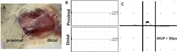
Figure 11. Morphological and electrophysiological assessment in control group. (A) No tissue regeneration was observed in the nerve gap region after 12 months, (B) no action potential could be detected by nerve conduction studies, (C) MUP recorded in the gastrocnemius region.
Download figure:
Standard image High-resolution imageThe SFI of animals implanted with PASF nanocomposite conduits was found to be −61 and −51 after 6 and 12 months respectively. Schwann cell seeded PASF conduits exhibited SFI of −58 and −47 after 6 and 12 months respectively. SF conduits exhibited SFI of −79 and −72 after 6 and 12 months post implantation respectively. SFI of animals with Schwann cell seeded SF conduits were found to be −79 and −70 after 6 and 12 months post implantation respectively. In comparison animals of control group exhibited SFI of −100 upto 12 months (figure 12).
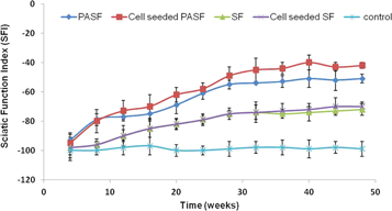
Figure 12. Sciatic function index (SFI) calculated through walking track analysis.
Download figure:
Standard image High-resolution image3.8. Morphological analysis of regenerated sciatic nerve
The untreated animals with sciatic nerve transection (control group) did not exhibit any tissue regeneration and both the proximal and distal stumps were found to have receded thereby lengthening the nerve gap (figure 11(A)). In the treated groups, the implanted conduits were observed to be stable with no dislocation or deformation when the surgical area was reopened after 6 and 12 months. Further the surrounding tissue also appeared to be morphologically normal in all the experimental groups. Histological analysis of the regenerated nerve indicated cellular recruitment inside the PASF nanocomposite conduits (both with and without cell groups) (figure 13). TEM analysis confirmed the deposition of myelin sheath visualized as black layering over axons in the regenerated tissue from inside the nanocomposite conduits (figures 14(B)–(D)). In contrast, animals implanted with SF conduits showed less cellular migration inside the nerve gap. Some cellular infiltration was evident inside the cell seeded SF from histological analysis but TEM studies revealed fragmented myelination of the regenerating axons among the animals having SF conduits (both with and without cells) (figures 13 and 14(E)–(H)).
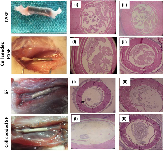
Figure 13. Gross and histological examination. Nerve conduits were harvested for gross observation and histological examination by hematoxylin-eosin staining after (i) 6 months and (ii) 12 months of implantation.
Download figure:
Standard image High-resolution image
Figure 14. Ultra structure of regenerated tissue under TEM. (A) Normal sciatic nerve, (B) regenerated tissue through PASF conduits one year post implantation, (C) regenerated tissue through cell seeded PASF conduits one year post implantation, (D) higher magnification image of myelin sheath deposited on a single axon in animals implanted with cell seeded PASF conduits after one year, (E)–(F) regenerated tissue through SF conduits one year post implantation, (G)–(H) regenerated tissue through cell seeded SF conduits one year post implantation.
Download figure:
Standard image High-resolution image
4. Discussion
Fabrication of a polyaniline blended poly(L-lactic acid-co-3-caprolactone) (P(LLACL))–silk fibroin (SF) composite electrospun nanofibrous mesh has been previously reported to facilitate neuronal cell proliferation [14]. The study was conducted with commercially available high molecular weight polyaniline (15 kDa) and limited to exploring the compatibility of polyaniline-based nanofibers with neuronal PC12 cells [14]. However the safety and efficacy of polyaniline-based nerve conduits in promoting functional regeneration of nerves remain unaddressed by preliminary in vitro studies. Hence we focused our work on synthesizing low molecular weight polyaniline oligomers to blend with silk fibroin and fabricate tubular nerve conduits for long-duration in vivo studies.
In the present study, polyaniline powder was synthesized following previously reported literature [17, 18]. The amphiphilic aniline monomer in the presence of strong acid releases anilinium cations and forms micelles which act as a template for the polymerization reaction. The polyaniline powder was observed to undergo aggregation and was amorphous in nature which could be due to the high monomer to APS ratio [26] (figure 1(A)).
The biocompatibility of synthetic conducting polymers has always remained a major concern, limiting their widespread use in biomedical applications. Extensive in vivo biocompatibility studies found that polyaniline did not induce any skin irritation or sensitization in humans and guinea pigs respectively [27]. Further the cytotoxic effects of conducting polymers like polyaniline/polypyrrole have been reported to vary widely between cell lines [28, 29]. In the present study we found the synthesized amorphous polyaniline powder to be non-toxic to rat Schwann cells (SCTM41) at lower concentration of 100 μg ml−1 as well as at the highest concentration of 1000 μg ml−1 when cellular viability was observed to be 80% of the control (figure 1(B)). This was further corroborated by live–dead assay experiments with AO (green fluorescence) and EB (red fluorescence) showing normal cellular morphology up to a PA concentration of 1000 μg ml−1 (figures 1(C)–(H)). Cells treated with 5% DMSO were considered as the positive control group since at this concentration it is a proven cytotoxic agent [30]. The cells showed limited green fluorescence and high red fluorescence along with rounded cellular morphology indicating cell death (figures 1(I)–(K)).
The molecular weight distribution of a polymer is essential for analyzing its physical, chemical and biological properties. The molecular weight of synthesized polyaniline has been previously studied using chromatographic techniques [31]. However, the solubility of the sample in an organic solvent is an essential prerequisite to obtain accurate results by chromatography. Polyaniline has been reported to be almost insoluble in any solvent and only exists in a dispersion state when mixed with organic solvents [32]. Hence, to obtain an accurate molecular weight distribution of polyaniline, we performed MALDI with and without solvent. Polyaniline primarily produces three types of oligomers based on the presence/absence of terminal amine (–NH2) which differ by a m/z value of 16 (figure 3) [22]. Further, the addition of one phenyl group (–C6H4NH–) to the oligomer chain led to an increase of the m/z value by 91 [21].
Solvent-based MALDI of polyaniline using acetonitrile and THF produced prominent peaks corresponding to 6 mer (m/z = 542, 558, 574), 7 mer (m/z = 634, 650, 666) and low intensity peaks for 8 mer (m/z = 725, 741). Polyaniline mixed in THF produces an additional peak for 8 mer around m/z = 757 corresponding to the structure depicted in figures 2(A), (B). Solvent-based MALDI analysis of polyaniline could detect oligomers upto a maximum of eight repeat units since only very low molecular weight portions are sparingly soluble in organic solvents like acetonitrile and THF (figures 2(A), (B)).
In order to detect higher molecular weight oligomers we performed solventless MALDI. The peaks for the oligomers in this case were observed to be of much higher intensity as compared to solvent-based MALDI and polymers with up to 12 repeat units were detected (figures 2(C), (D)). The results provide a strong indication that solventless MALDI is an ideal method to study molecular mass spectrometry of insoluble polymers like polyaniline and can also detect higher oligomers more efficiently as compared to conventional solvent-based techniques.
In the present study, aggregates of low molecular weight polyaniline were blended with silk fibroin protein in formic acid to form composite nanofibers through electrospinning (figures 4(A), (B)). However, since PA is insoluble in formic acid and exists in a dispersed state it was observed that the aggregates were broken down to nano dimensions during electrospinning thereby forming a uniform covering of polyaniline nanoparticles (average size 40–60 nm) over the silk nanofibers (figure 4(C)). Consequently, the average diameter of the PASF nanofibers (350–450 nm) was found to be larger than pristine SF fibers (150–250 nm) (figure 4(D)).
Polyaniline-based composite scaffolds have been previously demonstrated to support adhesion and differentiation of neuronal cells [33]. In our study, both PASF and SF nanofibers were found to support adhesion of Schwann cells (figures 4(E), (F)). The nanofibrous scaffolds (both PASF and SF) by virtue of their higher surface area were able to support growth and proliferation of cells for a longer time as compared to the control (figure 4(G)).
The resistance of silk fibroin was observed to decrease 12-fold upon addition of polyaniline powder in a very low concentration (1% of silk fibroin). A further decrease in resistance could be achieved by increasing the concentration of polyaniline in the polymer blend (data not shown), however, the propensity of PA powder to produce cytotoxic effects at higher concentrations led to its restricted use in the present study in order to balance electrical conductivity and biocompatibility [27].
The electrospun mats (SF and PASF) were characterized by FTIR and XRD analysis and compared with polyaniline powder to confirm the formation of composite nanofibers (figures 5(A)–(D)). The PASF nanocomposite mat exhibited a FTIR peak around 1614 cm−1 which correlates to 1668 cm−1 absorbance peak in SF for amide I and 1635 cm−1 peak present in PA powder corresponding to quinone ring C=N stretching vibration [34, 35]. The lower frequency 1541 cm−1 peak of the PASF nanocomposite can be attributed to 1579 cm−1 benzenoid diamine ring stretching of PA as well as the amide II region (1514 cm−1) of SF nanofibers [34, 35]. Similarly the peak at 1246 cm−1 for PASF nanofibers can be ascribed to the amide III structure of SF at 1240 cm−1 and the characteristic C–N stretching of PA [34, 35]. A small peak was observed around 1146 cm−1 in the SF electrospun mat corresponding to aliphatic amine whereas a broad peak around 1119 cm−1 was exhibited by PASF nanocomposite scaffolds. However no similar peak was found in the polyaniline powder, which is comprised entirely of aromatic amines. A series of small peaks observed at 931, 777, 725, 644, 517 cm−1 in PA powder can be ascribed to out-of-plane deformation of C–H [27, 34]. These were observed to be merged together forming a broad peak around 690 cm−1 in the PASF nanocomposite mat (figure 5(A)).
The crystalline form of polyaniline has been reported to exhibit three characteristic XRD peaks at 2θ = 15°, 20° and 25° corresponding to (011), (020) and (200) crystal planes with the one at 25° being the dominant peak [26, 34, 36]. However, we observed only a small and broad peak at 2θ = 24° for the synthesized PA powder (figure 5(D)). It indicates the low crystallinity and comparatively higher amorphous nature of the synthesized PA powder which is due to the high monomer (aniline) to APS ratio used during synthesis [26]. The XRD pattern of SF electrospun nanofibrous mat exhibited a broad peak around 2θ = 21° characteristic of amorphous silk fibroin protein in β-sheet configuration (figure 5(C)) [37]. The PASF nanocomposite sheet showed two peaks around 2θ = 20.65° and 2θ = 24.8° indicating the formation of a composite comprising amorphous silk fibroin and polyaniline (figure 5(B)).
Polyaniline generally exhibits three major weight losses by TGA around 100 °C, 200 °C and 500 °C corresponding to water loss, loss of acid molecules and decomposition of the polymer respectively [38]. In the present study, PA was thoroughly dried and hence limited weight loss around 100 °C was observed. A major weight loss occurred between 205 °C and 352 °C which can be attributed to the loss of hydrochloric acid molecules used as dopant. The polymer was found to steadily decompose to below 45% of its initial weight by 700 °C (figure 6). Silk fibroin nanofibers showed a major weight loss around 245 °C due to thermal degradation of the protein and continued until 464 °C before becoming stable up to 700 °C (figure 6) [39]. PASF composite nanofibers exhibited thermal properties similar to that of pure silk fibroin since the PA concentration was restricted to only 1% of the composite. The sharp weight loss around 246 °C points to the degradation of silk fibroin. The composite continued to degrade with increase in temperature and less than 45% of initial weight remained up to 700 °C (figure 6).
The electrospun sheets (both SF and PASF) were peeled off and rolled over a needle of appropriate diameter to form a nerve conduit. Multiple rotations of the electrospun sheet created a lamellar architecture of the nerve conduit which mimics the layer by layer deposition of myelin by Schwann cells over axons (figures 7(A)–(F)) thereby supporting adherence and proliferation of cells. Additionally, such stacking and rolling of multiple layers of densely arranged nanofibers contributed to the overall low porosity and swelling tendency of the conduits (figure 8).
The size of polyaniline particles have been found to influence the cytotoxicity and its nanoform in particular has been reported to be highly toxic at concentrations above 10 μg ml−1 causing cell death, increased cellular reactive oxygen species and disturbed mitochondrial membrane potential [40]. Since the PASF nanocomposite fibers comprised polyaniline nanoparticles it was essential to confirm their biocompatibility through intracutaneous skin irritation and toxicity studies. However no adverse immunogeneic or toxic response was noted among the animals (both PASF and SF groups), which may be attributed to the strong interaction between PA nanoparticles and SF protein which prevents any washout of nanoparticles into the saline extract (figure 9(A)).
Functional neuro-regeneration was evaluated through electrophysiological studies. The CMAP waveforms for all the experimental groups are depicted in figure 10 and the quantitative analysis of CMAP and NCV are represented in table 1. The animals implanted with PASF conduits (both with and without cells) showed an appreciable improvement in wave pattern with enhanced amplitude and higher area under the curve with time from 6 to 12 months. A similar trend was also observed with animals having SF conduits (both with and without cells) after 6 and 12 months. However, the nanocomposite group with PASF conduits (both with and without cells) clearly outperformed the animals with plain SF conduits (both with and without cells) with higher NCV and CMAP values after 12 months indicating better functional regeneration of the transacted nerve. The animals implanted with Schwann cell seeded PASF conduits exhibited recovery as high as 86.2% of NCV and 80.00% of CMAP as compared to normal rat thereby suggesting the positive role of Schwann cell seeding in enhancing nerve regeneration outcomes. The animals that were left untreated (control group) did not exhibit any action potential over a period of 12 months indicating the absence of regenerated neural tissue across the gap (figure 11(B)).
Nerve conduction studies and CMAP analysis form only a part of complete peripheral neurophysiological examination and are generally accompanied by monitoring MUP recorded from the surrounding muscle area through needle EMG. Since sciatic nerve is the major mixed nerve innervating the gastrocnemius region we conducted MUP measurements through needle EMG to evaluate the neuromuscular regeneration in the region. The animals implanted with PASF conduits seeded with Schwann cells exhibited highest MUP after 12 months corresponding to 76.07% of MUP of normal rat (table 1). The result indicates enhanced re-innervations of the gastrocnemius muscle fibers with regenerated axons. MUP recorded from the untreated animals (control group) exhibited a minute potential of 30 μV, which could be attributed to smaller nerves other than the sciatic nerve that also innervate the gastrocnemius muscle fibers (figure 11(C)).
The SFI calculated from walking track analysis is still one of the most preferred non-invasive ways to objectively assess recovery of motor function [41]. A SFI score of −100 indicates the complete inability to walk and severely damaged gait whereas a normal walking pattern gives an SFI score of 0. The untreated animals (with a nerve gap and without any nerve conduit) exhibited a constant SFI of around −100 for 12 months (figure 12). Sequential improvement of SFI was observed in all experimental groups with a saturation point after 32 weeks (figure 12). Animals having SF conduits with and without cells showed a SFI improvement up to a maximum of −70 and −72 respectively. In comparison Schwann cell seeded PASF conduits exhibited the best gait pattern with an SFI of −47 which was much improved than the animals with PASF conduit having an SFI of −51.
The conduits were harvested from the animals 6 and 12 months post implantation and the tissue within the nerve gap was histo-morphometrically analyzed to evaluatie the extent of neuro-regeneration through the conduits (figure 13). A low amount of cellular growth was observed across the lumen of SF and cell seeded SF conduits after 6 months. However, after 12 months, accumulation of inflammatory cells inside the conduit was observed in SF and SF cell groups. The culture of Schwann cells over the nanocomposite PASF conduits evidently led to a higher amount of normal neuronal cells inside the lumen facilitating regeneration of nervous tissue across the gap. In the case of animals where no conduit was implanted (control group) the nerve gap increased considerably on both ends and no signs of neural regeneration were observed even after 12 months (figure 11(A)). Although some portion of the proximal end was visible the distal nerve stump was found to have completely degenerated.
The process of myelination is an important indicator of accurate neuron–glia interaction, which is essential for complete neural regeneration and can be evaluated by staining tissue sections with lipid binding dyes like osmium tetra oxide, toluidene blue etc [42]. The black coating observed around axons after osmium tetraoxide staining of the samples under TEM indicates deposition of myelin by Schwann cells (figure 14). A closer look at the ultrastructure of the tissue harvested from the lumen of cell seeded PASF conduits revealed thick deposition of myelin in a lamellar fashion similar to normal nerves (figure 14(A)) thereby indicating proper myelination of the regenerating axons (figures 14(C), (D)). In comparison, the thin, discontinuous and granular type deposition of myelin observed in the regenerating tissue of SF conduits (with and without cells) (figures 14(E)–(H)) points to incomplete and improper myelination, which explains the low NCV, CMAP and MUP values observed in animals belonging to SF groups (with and without cells).
Although conductive polymer-based scaffolds have been extensively studied for potential use as nerve conduits, in vivo studies for evaluating nerve regeneration in animal models have been very limited [9, 10, 16, 43]. Further these in vivo studies have been for a short duration (maximum 16 weeks) and without complete electrophysiological analyses. In the present study, we observe the effects of a synthetic conducting polymer like polyaniline in vivo over a long duration (1 year) and evaluate functional nerve regeneration through several electrophysiological tests like NCV, CMAP and MUP including walking track analysis. The animals implanted with Schwann cell seeded nanocomposite PASF conduits exhibited excellent NCV and CMAP patterns along with high MUP values, which are better than previous reports of nerve regeneration using similar electrically conducting nerve conduits [9, 16]. These electrophysiological results along with thick myelination in a lamellar fashion strongly indicate superior functional and morphological regeneration of nerves in the PASF group as compared to previously reported conducting polymer-based nerve conduits.
5. Conclusions
The present study demonstrates the fabrication of polyaniline–silk nanocomposite-based tubular conduits by electrospinning and subsequent rolling of the electrospun sheet. The extensive in vitro and in vivo toxicity studies prove the biocompatibility of polyaniline. Further the fact that the PASF nanocomposite nerve conduits did not elicit any immune response or graft rejection over a period of one year upon implantation establishes the safety of polyaniline-based scaffolds for biomedical applications. The study also demonstrates the efficacy of pre-seeding nerve conduits with Schwann cells in enhancing neural regeneration outcomes. The excellent electrophysiological parameters obtained after 12 months of implantation of polyaniline-based nerve conduits along with cellular recruitment and thick lamellar deposition of myelin over regenerating axons should encourage further in vivo studies using conducting polymers to develop biocompatible electrically conductive nerve conduits.
Acknowledgments
We would like to thank and acknowledge Central Silk Board, Bengaluru, Govt of India (Sanction order no: CSB-31/2/PROJECT/2010-11-RCS dated 26.05.2011) and Department of Biotechnology, New Delhi, Govt of India (Sanction order no: BT/PR14042/MED/30/338/2010 dated 04.01.2011) for providing partial funding support for this work. SD would like to thank IIT Guwahati and Ministry of Human Resource Development (MHRD), Govt of India for providing financial assistance in the form of a PhD fellowship.
Conflict of interest
A portion of the work reported in the present article has been used to file an Indian patent application vide application number 721/KOL/2015.