

Abstract
We demonstrate Limaçon-shaped micro-cavity lasers with directional emission. In experiments, this kind of micro-cavity laser was fabricated with a deformed factor of ε = 0.41, characterized and compared with a traditional F–P cavity ridge laser prepared with the same material at a wavelength of about 10 μm. From the experimental results, the micro-cavity laser showed highly directional emission (of about 9 mW output peak power) with a parallel directional divergence angle of 30° and a perpendicular divergence angle of 67° at full width at half maximum, which is similar to that of the ridge laser. The threshold current density of the micro-cavity laser was about 40% lower than that of the ridge laser, and the quality factor was estimated to be up to 1140.
Export citation and abstract BibTeX RIS
1. Introduction
Micro-cavity lasers have attracted a great deal of attention due to their low threshold, high quality factor Q and being suitable not only for high density optoelectronic integration applications, but also for fundamental studies such as cavity quantum electrodynamics and nonlinear optical processes [1, 2]. Micro-cavity lasers have low threshold current densities, but their optical output power is very low due to the total internal reflection of the whispering gallery modes (WGMs), and their far-field profiles are normally isotropic. To overcome these intrinsic problems of traditional micro-disk lasers, various deformed structures have been proposed and, up to now, directional emission has been found in cavities of spiral, rounded isosceles triangular, and stadium-shaped lasers [3–5]. Even though the deformed cavities generate directional emission, the Q-factor degrades as the deformation parameter increases. Recently, a Limaçon-shaped cavity structure was reported [6], where the lasing modes are emitted with directionality with high Q-factors. Since then, experimental investigations have followed to investigate the lasing behavior of the Limaçon-shaped micro-cavity laser in quantum cascade lasers, quantum dot lasers, and InGaAsP semiconductor lasers [7–9]. These reports have normally focused on the characterization of the parallel emission pattern of micro-cavity lasers. However, the perpendicular beam divergence angle of a laser is also an important aspect for all laser device applications, especially for the coupling to the waveguides and photonic integration applications. Moreover, there is no detailed report, to the best of our knowledge, on comparison of the characteristics of micro-disk cavity lasers with traditional F–P cavity ridge lasers. In this paper, we investigate both the parallel and the perpendicular divergence angles of a Limaçon-shaped micro-cavity laser with deformed factor ε = 0.41 fabricated with InGaAs/InAlAs quantum cascade material at about 10 μm wavelength, since QC lasers are especially suited for the disk geometry due to their lack of surface recombination and inherently in-plane transverse-magnetic (TM) mode emission [10]. Furthermore, the performance of the micro-cavity laser is compared with a ridge laser fabricated from the same materials, with regard to the far-field pattern, threshold current and light output power. Finally, the quality factor Q of the micro-cavity laser is estimated from the measured threshold current density result.
2. Device structure and fabrication
In this work, we used electrically pumped QC laser material as an example to fabricate the micro-cavity laser. The electrical pumping scheme requires a relatively large top surface area (dimension > 50 μm) for electric wire bonding which defines the comparatively large size of our cavities. A Limaçon-shaped cavity structure is shown in figure 1(a). Its edge can be expressed in polar coordinates as

where R0 is the radius of curvature when θ = π/2, and ε is the deformation factor of the cavity structure [6]. If the deformation factor ε = 0, it degenerates into a circular cavity.
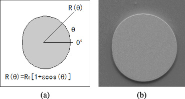
Figure 1. (a) Schematic structure of a Limaçon-shaped micro-cavity structure; (b) scanning electron microscope image of the Limaçon-shaped cavity laser.
Download figure:
Standard image High-resolution imageThe micro-cavity structure was prepared on lattice matched Ga0.47In0.53As/Al0.48In0.52As QC laser material, which was grown by molecular beam epitaxy (MBE) on top of an n-doped (3 × 1018 cm−3) InP substrate. The laser material was built from alternate stacks of an active region formed by coupled QWs and a superlattice injector region that served as an energy relaxation region for electrons exiting the previous stage, which was designed at an emission wavelength of λ ≈ 10 μm. The active region was sandwiched between two n-doped (3 × 1016 cm−3) InGaAs layers, which were followed by 3.5 μm-thick n-doped (1 × 1017 cm−3) InP cladding layers. A 0.5 μm-thick n-doped (5 × 1018 cm−3) InP layer was deposited on top of the cladding layer, followed by a highly n-doped (1 × 1019 cm−3) InGaAs contact layer.
A standard photolithography process was employed to define the contour of the micro-cavity laser and the structure was etched through the gain medium with a depth of about 10 μm using inductively coupled plasma reactive ion (ICP-RIE) etching with a SiO2 mask to obtain vertical sidewalls. The parameters of the fabricated micro-cavity laser were R0 = 90 μm and ε = 0.41. For pumping, a top metal contact, Ti/Au (20 nm/200 nm), was deposited on top of the micro-cavity structure, and then the substrate was thinned to about 130 μm to reduce the series resistance and improve the thermal spreading effect; finally the bottom contact was made by Ti/Au deposition on the thinned substrate. Figure 1(b) shows a scanning electron microscope image of a micro-cavity laser. The devices were then soldered epilayer up on copper heat sinks with indium solder, and then wire bonded for experimental characterization.
We also prepared a traditional F–P cavity ridge laser with a similar cavity volume from the same material in order to compare the performance of the micro-cavity laser with that of the ridge laser. In the ridge laser structure, the width of the ridge was 16 μm and the cavity length was 1.6 mm. The cavity length of the ridge laser was formed by cleavage of the wafer along the natural crystal surface, while the micro-cavity laser needed no further cleavage process to form a resonance cavity. The ridge laser was then bonded epilayer up on a copper heat sink with the same process as used in the fabrication of the micro-cavity laser.
3. Device characterization and comparison
The processed devices were electrically pumped and tested in pulsed mode at room temperature with 100 ns current pulses at 10 kHz repetition rate. The light output was collected from the micro-cavity laser with a calibrated thermopile detector, and reached up to 9 mW in peak power. The device was mounted on a rotational stage to measure the far-field pattern.
3.1. Far-field patterns
The parallel far-field profile of the device was measured with a resolution of 0.5° using a setup based on a motorized rotation stage. The device was mounted in the center of a rotation stage and a mid-infrared mercury–cadmium telluride detector was placed about 20 cm away to measure the output of the laser. The measurement was performed over a 360° scanning range. The measured parallel far-field pattern of the micro-cavity laser is shown in figure 2(a) for a constant pumping current of 840 mA, which is approximately 1.5 times the threshold current (Ith = 0.56 A, as shown in figure 5(a)). We observed evident light output emission in the direction of 0° from the orientation of the Limaçon-shaped device with ε = 0.41, and the far-field divergence angle defined as the full width at half maximum (FWHM) was about 30°.

Figure 2. (a) Measured far-field pattern of the micro-cavity laser; (b) calculated far-field pattern of the micro-cavity laser.
Download figure:
Standard image High-resolution imageThe parallel far-field pattern of the Limaçon-shaped cavity laser was calculated with ray optics simulations in so-called Fresnel billiards using an effective index of refraction neff = 3.2 in order to support the experimental result further. The simulation was carried out by starting a set of 30 000 rays along the cavity boundary with whispering gallery like mode initial conditions (0.8 < |sin(χ)| < 1, χ is the angle of incidence); the detailed calculation method can be found in [6, 7]. The rays propagate following the laws of specular reflection. Light escaping the cavity according to Snell's law was collected as the far-field characteristics. From the calculation, as shown in figure 2(b), a visual emission direction from the cavity is presented around the 0° line in polar coordinates. Comparing figures 2(a) and (b), good agreement between the experiment and the simulation is displayed. The slight difference is most likely due to the unavoidable sidewall surface scattering.
The inset of figure 3 shows the parallel far-field divergence angle of the directional emission from the micro-cavity laser around the 0° line in the Cartesian coordinate system; the parallel divergence angle at FWHM is θ∥ = 30°.

Figure 3. Measured far-field parallel divergence angle θ∥ and perpendicular divergence angle θ⊥ for the micro-cavity laser.
Download figure:
Standard image High-resolution imageBy rotating the laser by 90°, the beam divergence perpendicular to the quantum well plane was also measured, as shown in figure 3. Although some slight asymmetry is observed in the perpendicular far-field pattern, the general emission seems to be mainly in a single mode; the perpendicular divergence angle at FWHM is θ⊥ = 67°.
The far-field characteristics of the ridge laser are shown in figure 4. The experimental data were obtained by the measurement taken at an injection current of 1.3 A, which is approximately 1.5 times the threshold current (Ith, ridge = 0.9 A, as shown in figure 5(b)). The far-field divergence angles in the parallel direction, θ∥, and perpendicular direction, θ⊥, are 33° and 66° at FWHM, respectively.
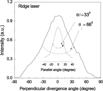
Figure 4. Measured far-field parallel divergence angle θ∥ and perpendicular divergence angle θ⊥ for the ridge laser.
Download figure:
Standard image High-resolution image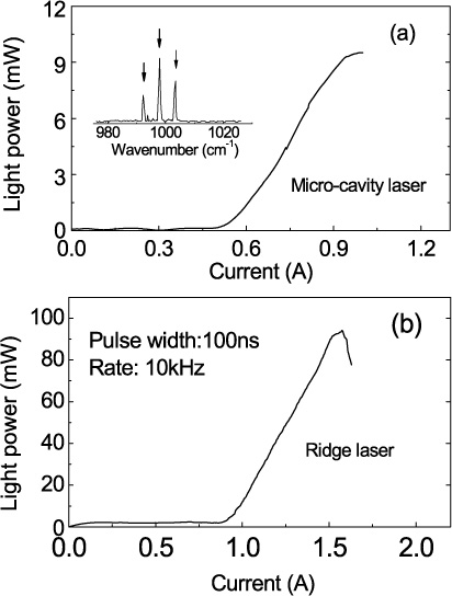
Figure 5. (a) Measured light output peak power as a function of current for the micro-cavity laser; inset: measured light spectrum of the micro-cavity laser; (b) measured light output peak power as a function of current for the ridge laser.
Download figure:
Standard image High-resolution image
By comparing the experimental data shown in figure 3 with those in figure 4, it is clear that the micro-cavity laser can produce nearly the same light output beam characteristics as the ridge laser. Along with the directional emission properties, the in-plane fabrication of the micro-cavity laser is very promising with respect to the realization of on-chip coherent light sources for monolithic photonic network integration applications.
3.2. Light output characteristics
The light output power was measured by using a calibrated thermopile power meter, positioned around the 0° line of the directional emission of the micro-cavity laser, and the collection of the light output emission was about 100°.
Figure 5(a) shows the light output peak power–current (L−I) curve of the micro-cavity laser, and an output peak power of about 9 mW was obtained due to the inefficient light output coupling from the micro-cavity structure compared with the output peak power of about 92 mW for the ridge laser, as shown in figure 5(b). Therefore, further improvement of the output power is still one area for future study for micro-cavity lasers.
The inset of figure 5(a) shows the emission spectrum of the micro-cavity laser by adopting a high-resolution Fourier transform infrared spectrometer; the peak lasing wavelength is about λ = 10.03 μm (wavenumber: 997 cm−1). The average mode spacing is approximately 5.51 cm−1, which is in good agreement with the calculated value of 5.53 for WGMs, given by the theoretical calculation 1/(L × neff), where L is the perimeter of the micro-cavity and neff is the effective refractive index of the material.
3.3. Threshold current and quality factor
From figure 5(a), the threshold current of the micro-cavity laser is Ith = 0.56 A, corresponding to a threshold current density of 2.20 kA cm−2, which is about 40% lower than that of the edge-emitting laser with Ith, ridge = 0.9 A, as shown in figure 5(b), corresponding to a threshold current density of 3.5 kA cm−2.
The quality factor Q of micro-cavity lasers can be estimated by using the basic relation [10]

where neff is the effective refractive index, λ0 is the wavelength in vacuum, Jth is the threshold current density, g is the gain coefficient, and Γact is the optical confinement factor for the active region. The value of gΓact can be derived from the relation of the cavity length of the ridge laser to the threshold current density (Jth, ridge), expressed as [11]

where αw is the waveguide loss and αm is the cavity reflection loss,  , where L is the cavity length and R is the reflectivity. We deduced gΓact = 8.0 × 10⁻³ cm A−1 from ridge laser devices processed with different cavity lengths. Then the quality factor of the micro-cavity laser is estimated as Q = 1140. Surface roughness can reduce the Q factor of micro-cavity lasers, and the Q factor could be improved by further smoothing the surface of the cavity in future work.
4. Conclusion
We demonstrated a Limaçon shaped micro-cavity laser with a deformation factor of ε = 0.41 based on InGaAs/InAlAs QC laser material, and compared its performance with a traditional F–P cavity ridge laser. The micro-cavity laser shows highly directional emission with a far-field divergence angle of 30° × 67° at FWHM, which is similar to the beam divergence angle measured for the ridge laser. The output peak power is up to 9 mW. The threshold current density is about 2.20 kA cm−2, which is about 40% lower than that of the ridge laser. Finally, the quality factor of the micro-cavity laser is estimated as Q = 1140. Therefore, the micro-cavity laser, combining directional emission, low threshold current density and on-chip fabrication characteristics, can be considered to be a useful device in optoelectronic integration applications.
Acknowledgments
This work was partially supported by CUST&Jilin projects 62201050303-2 and 20130521014JH. The authors would like to thank Dr Qijie Wang at Nanyang Technological University for helpful support.