Abstract
A novel method for fabricating all-solid flexible microsupercapacitors (MSCs) was proposed and developed by utilizing screen printing technology. A typical printed MSC is composed of a printed Ag electrode, MnO2/onion-like carbon (MnO2/OLC) as active material and a polyvinyl alcohol:H3PO4 (PVA:H3PO4) as solid electrolyte. A capacity of 7.04 mF cm−2 was achieved for the screen printed MnO2/OLC MSCs at a current density of 20 μA cm−2. It also showed an excellent cycling stability, with 80% retention of the specific capacity after 1000 cycles. The printed all-solid flexible MSCs exhibited remarkably high mechanical flexibility when the devices were bent to a radius of 3.5 mm. In addition, all-solid MSCs were successfully demonstrated by screen printing technique on various substrates, such as silicon, glass and conventional printing paper. Moreover, the screen printing technique can be extended to other active materials, such as OLC and carbon nanotubes. This method provides a general route for printable all-solid flexible MSCs, which is compatible with the roll-to-roll process for various high performance active materials.
Export citation and abstract BibTeX RIS
1. Introduction
A microsupercapacitor (MSC) is a new type of supercapacitor with typical device feature sizes in the range of micrometers. It is deemed to be one of the ideal power sources for driving miniaturized electronic devices such as microelectromechanical systems (MEMS) or on-chip electronics [1, 2]. Compared to conventional supercapacitors, MSCs not only have high capacities, power densities and charge/discharge rate, but also large energy densities due to the reduced diffusion length [2, 3]. Recently, pseudo-supercapacitors have attracted substantial research interest and various active materials have been developed which continuously improve the performance of supercapacitors [4–7]. Pseudo-supercapacitors enable the faradic or redox process between the electrode and electrolyte interface, which results in a larger capacity and energy density compared to conventional double layer supercapacitors[8, 9]. Considering these attractive features, miniaturized pseudo-supercapacitors are anticipated to be an effective device design for MSCs.
In the fabrication processes, various active materials may require different techniques which need to be fully understood for the device design, consolidation and testing procedures. For example, the laser writing (or scribing) method has successfully demonstrated for graphene or graphene oxide MSCs [10, 11]; however, it is not suitable for metal oxide (a group of pseudo-supercapacitor active materials) MSCs. Apart from direct laser writing/scribing [10–13], multiple technologies have been designed and developed for the fabrication of special MSCs, such as rolled-up multilayer nanomembranes [14], origami [15], conventional microelectronic fabrication [3, 5, 15–24], electrochemical deposition [25, 26], ink-jet printing [27], electrostatic spray deposition [28] and deep etching [29]. Although some methods have been developed for metal oxides MSCs, such as conventional microelectronic fabrication with the assistance of the high temperature growth of carbon nanotubes (CNTs) and electrochemical deposition of metal oxides [18], they are all designed for specific active materials which normally involve a complicated fabrication process, various chemical treatments, high temperature and high cost, resulting in hurdles and difficulties for large areas and mass production. In particular, the high temperature is not compatible with the low cost polyethylene terephthalate (PET) and/or paper flexible substrates for wearable devices or technologies [30]. Ink-jet printing technology is a drop-on-demand technology, which can accomplish the deposition and patterning in the same step, reducing material usage and process complexity [31, 32]. Carbon material (graphene and CNT) devices have been fabricated by ink-jet printing methods [27, 33]. However, only a handful of inorganic materials have been ink-jet printed, as it is difficult to prepare stable and jettable precursor ink, leading to the slow development of printing technology in MSC fabrication [34]. Besides the limitations for device fabrication techniques, most of the research efforts have been on the particular active materials for supercapacitors [35] and general routes are rarely reported in the literature.
Herein we used a simple method based on screen printing technique to fabricate all-solid flexible MSCs based on metal oxides/carbonaceous active materials and investigate their electrochemical properties with various bending angles. Screen printing is a printing technique that uses a woven mesh to support an ink-blocking stencil to obtain a desired image [36]. During the printing process, the ink can be pressed through the opening of the mesh to form the pattern on the substrate. It is a mature technique for patterning on various substrates, such as cloth and paper. Screen printing technique has been used for electronic device fabrication, such as field effect emission devices [37], and roll-to-roll transparent electrodes [38]. As the ink is pressed through the openings of the mesh, various nanomaterials can be directly printed on flexible substrates for MSCs. The demonstrated method opens up a general route for fabrication of new active material MSCs, electrochemical performance investigation and roll-to-roll mass production.
2. Experimental section
Silver (Ag) conductive paint was purchased from SPI Supplies, USA. Carbon black was purchased from Alfa. Polyvinyldifluoride (PVDF), N-methylpyrrolidone (NMP), polyvinyl alcohol (PVA) and H3PO4 were purchased from Sigma-Aldrich. CNTs (L-MWNTs-60100) were purchased from Shenzhen Nanotech Port Co., Ltd, Shenzhen, China. All chemicals were used directly without further purification or any treatment.
There are three steps for fabricating the all-solid MSCs: electrode printing, active material printing and electrolyte deposition (shown in figure 1(a)). First, Ag electrodes were printed by the screen printer on the bare polyethylene terephthalate (PET) substrate, followed by drying and annealing in a vacuum oven at 200 °C for 1 h. Subsequently, the active material ink was printed on top of the Ag electrode, followed by drying at 110 °C in a vacuum oven. Details on the synthesis of the active material (MnO2/onion-like carbon (MnO2/OLC)) and the ink preparation process can be found in our previous report [39]. Typically, 80 wt% active material, 10 wt% conductive carbon black (if necessary) and 10 wt% PVDF binder in NMP were mixed to form a homogeneous slurry. Finally, the PV A/H3PO4 electrolyte sol was coated on top of the device to cover the channel area, followed by drying naturally in air more than 12 h. A typical solid electrolyte can be prepared by the following steps: 3 g PVA and 3 g H3PO4 were added into 30 ml de-ionized (DI) water at 80 °C with vigorous stirring for 1 h until the precursor solution became transparent [40].
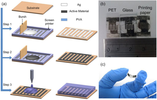
Figure 1. (a) Schematic diagram of the fabrication process. (b) Photo of the all-solid MSC devices printed on PET, glass and A4 printing paper substrates. (c) Photo showing the flexible property of the printed all-solid flexible MSCs on a PET substrate. After the Ag electrode printing process, the samples on PET and glass substrates were heated at 200 °C and the samples on A4 printing paper were heated at 150 °C in a vacuum oven.
Download figure:
Standard image High-resolution imageThe morphology of the nanocomposites was examined by a LEO 2760 field emission scanning electron microscope (FESEM) and a JEM-2100F transmission electron microscope (TEM). The electrochemical properties of the MSCs were measured by an electrochemical workstation (VMP3, Bio-logic). Cyclic voltammetry (CV) was performed in the voltage range of 0–0.8 V at various scan rates. Electrochemical impedance spectroscopy (EIS) was carried out by applying a sinusoidal signal of 10 mV amplitude with frequencies from 1 M to 0.1 Hz. The galvanostatic charge/discharge test of the single device was studied in the voltage range of 0–0.8 V at various current densities from 20 to 200 μA cm−2.
3. Results and discussions
The MSCs can be fabricated onto various substrates, such as PET, glass and conventional A4 printing paper, as shown in figure 1(b). As we can see, a planar MSC is composed of two electrodes (negative/positive) in the same plane covered by the active material (black part) and a transparent electrolyte. Both the substrate and the electrolyte are solid and flexible. A picture of the bent MSC is displayed in figure 1(c) to show its flexibility.
Figures 2(a) and (b) show the FESEM and TEM images of the MnO2/OLC nanocomposites. We can see that the MnO2/OLC nanocomposites have a unique nano-urchin shape with a diameter in the range of 200–500 nm. This nano-structure material has been employed as the electrode material in a conventional supercapacitor and it exhibited an excellent electrochemical performance, which can be found from our previous studies [39]. It is difficult to grow or integrate such nanostructures into MSCs by the conventional microelectronic fabrication process directly. However, this is easily achieved with screen printing technology.
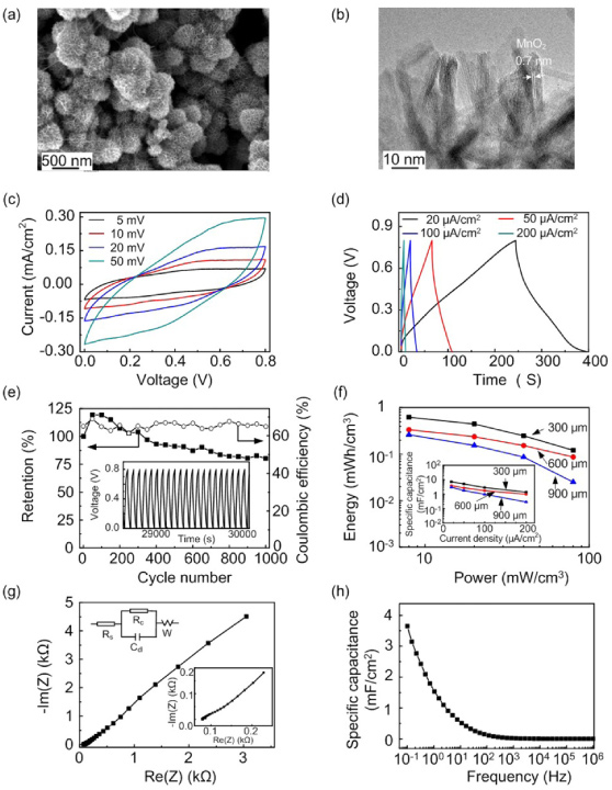
Figure 2. (a) FESEM and (b) TEM images of the MnO2/OLC. (c) CV at various scan rates. (d) Galvanostatic charge and discharge curves at various current densities and (e) cycling performance and related Coulombic efficiency of a single MnO2/OLC MSC with a channel length of 600 μm at the current density of 50 μA cm−2. The inset in (e) shows the charge/discharge curves. (f) Specific energy with the power density of the printed all-solid flexible MSCs with various channel lengths. The inset in (f) is the specific capacity at various current densities with different channel lengths. (g) Nyquist plot of the all-printed solid flexible MSCs with a channel length of 600 μm. The inset in (g) shows the high frequency region of the plot and the equivalent circuit diagram. (h) Frequency response of the specific capacitance of the printed all-solid flexible MSCs with a channel length of 600 μm calculated according (g).
Download figure:
Standard image High-resolution imageThe electrochemical properties of the MnO2/OLCnanocomposite MSCs are shown in figures 2(c)–(f). The CV was measured in the range of 0–0.8 V, as shown in figure 2(c), with various scan rates of 5−50 mV s−1 based on MSCs with a channel width of 600 μm. For comparison, the CV curve (100 mV s−1) of the bare Ag electrode-based MSCs without the active material is shown in figure S1(a) (available at stacks.iop.org/Nano/25/094010/mmedia). The response current of the bare MSCs is negligible compared to the MSCs with MnO2/OLC at the same scan rate. This result suggests the high charge storage ability originates from the MnO2/OLC active material. The galvanostatic charge/discharge was tested at various current densities and the results are shown in figure 2(d). The specific capacitance Cs was calculated according to equation (1)

where I is the charge/discharge current with a unit of μA, Δt is the discharge time with a unit of s, S is the area of the active material/electrode covered with the electrolyte with a unit of cm2, and ΔV is the potential drop during the discharge process. Therefore, the calculated specific capacities of our printed all-solid flexible MSCs are 3.80, 2.69, 1.73 and 0.98 mF cm−2 at current densities of 20, 50, 100 and 200 μA cm−2, respectively. Our printed all-solid MSC has a capacity of 3.80 mF cm−2, which is a bit higher than that of the conventional OLC-based MSC [41], laser direct written graphite oxide film (∼ 0.51 mF cm−2) [11] and the ink-jet printed CNT MSCs (0.4 mF cm−2) [27].
The cycling performance of MSCs is a critical parameter for practical applications. The retention capability of the MSCs as a function of the cycle number at a current density of 50 μA cm−2 for 1000 cycles is shown in figure 2(e). The capacity is increased during the first 100 cycles and then decreased slightly for longer cycles and still maintained 80% retention for 1000 cycles. Such good cycling performance demonstrates that our printed all-solid MSCs have excellent electrochemical stability for practical applications. In addition, the Coulombic efficiency (CE), with an average value of about 65% at a current density of 50 μA cm−2 for 1000 cycles, is also shown in figure 2(e). CE with various current densities is shown in figure S2 (available at stacks.iop.org/Nano/25/094010/mmedia). As we can see, CE is reduced with the decrease of the current density. CE is 74.8% for a current density of 200 μA cm−2,but it decreases to 62.1% for a current density of 20 μA cm−2. Therefore, the charge and discharge parts in figure 2(d) are not symmetric. The reason for the low CE and asymmetric charge/discharge parts is mainly due to the high self-discharge rate, as shown in figure S3 (available at stacks.iop.org/Nano/25/094010/mmedia). The device voltage dropped quickly during the first few seconds after charging to 0.8 V, and then gradually decreased after several minutes and remained almost stable at 0.1 V after 1 h. During the charge process, the charge current should compensate the self-discharge current first then charge to supercapacitor. During the discharge process, the actual discharge current is the measured discharge current with the self-discharge current. Further experiments need to be carried out to limit the self-discharge issue in the future.
The CV and galvanostatic charge/discharge curves for channel widths of 300 and 900 μm are shown in figure S4 (available at stacks.iop.org/Nano/25/094010/mmedia) and the energy densities with the power densities are summarized in figure 2(f), as well as the specific capacities with the various current densities. The calculation was based on a 10 μm thick printed active material layer, as indicated in figure S5 (available at stacks.iop.org/Nano/25/094010/mmedia). It can be seen that the MSCs with shorter channel widths have larger power density and higher capacity at the same energy density and current density, respectively. For example, the highest capacity was 7.04 mF cm−2 obtained from the MSCs with the shortest channel length (300 μm) at a current density of 20 μA cm−2. A similar phenomenon was also observed in previous reports [3, 12], which can be attributed to the shortened channel length leading to a faster response of the ions inside the electrolyte [3].
To further understand the electrochemical behavior of the all-solid printed MSCs, EIS was performed based on the MSC with a 600 μm channel length to evaluate its performance, as shown in figure 2(g), as well as the related equivalent circuit. The Nyquist plot (EIS) curve is composed of one semicircle (not obvious) in the high frequency region and a near-straight line at low frequency with an angle of 45°. In the fitted circuit, Rs is the electrolyte resistance which corresponds to the intercept of the semicircle with the x-axis in the high frequency regime [42]. Rc and Cdl are the contact interface resistance and the double layer capacitance, respectively, which correspond to the semicircle in the middle frequency regime [25]. W is the Warburg impedance relating to the ion diffusion mechanism, which corresponds to the straight line in the low frequency regime. The simulated values of Rs, Rc, Cdl and W are 78.59 Ω, 6909 Ω, 0.5 mF and 0.000 43 S s5, respectively. The double layer capacitance for unit area is 0.5 mF/0.396 cm2 = 1.264 mF cm−2, which agrees well with our measured capacitance (0.98−3.80 mF cm−2). The capacitance is also can be estimated from the Bode plot by using equation (2)

where f is the frequency and Z is the impedance [4]. As we can see from figure 2(h), with the decrease of the frequency the MSC behaves like a capacitor with a capacitance of about 3.7 mF cm−2 at a frequency of 0.1 Hz.
A bendable power source is critical for multifunctional flexible electronics and wearable devices in real applications, so the flexibility of the MSCs was tested with the configuration shown in figure 3(a), where the MSC was attached to the surface of a test tube. The bent radius can be estimated according to the radius of the attached tube. In actual applications, flexible MSCs can be stuck to the curved surface of the object. The CV performance of the printed solid MSCs was measured at a scan rate of 100 mV s−1 with various bending radii ranging from flat to 3.5 mm as shown figure 3(b). The shape and area of the CV curve change slightly with the decrease in the bending radius, indicating that the device can be bent arbitrarily without obvious degradation of performance. The flexibility is comparable to laser written graphene oxide flexible MSCs [12]. This excellent physical property can be attributed to the high mechanical durability of the printed electrode and the interpenetrating network structure between the printed porous active material film structure and the solidified electrolyte [10].

Figure 3. (a) Flexibility testing configuration and (b) CV of the printed solid flexible MSCs with various bending radii with a scan rate of 100 mV s−1.
Download figure:
Standard image High-resolution imageThe voltage of all-solid MSCs can be further increased by connecting individual devices in series, and the capacity can be improved by connecting the devices in parallel, leading to a longer working time. Figures 4(a) and (b) depict CV and galvanostatic charge and discharge curves at 19.8 μA (50 μA cm−2) with a potential window of 0–2.4 V (three times the potential window of a single device) of three MSCs connected in series, respectively, and the equivalent circuit is shown in the inset of figure 4(a). From the CV curves of figure 4(a), a three times enhanced potential window can be provided by three devices connected in series. Because the galvanostatic charge and discharge current of the three series connected devices is same as that of the single device and the potential is three times of that of the single device, the discharge time is identical to that of the single device, as shown in figure 4(b). In contrast, figures 4(c) and (d) illustrate CV and galvanostatic charge and discharge curves at 19.8 μA with a potential window of 0–0.8 V (the same as that of the single device) of three MSCs connected in parallel, respectively, and the equivalent circuit is shown in the inset of figure 4(c). From the CV curves in figure 4(c), the output current of three parallel connected devices is increased almost by a factor of three, as the effective area was increased three times when three capacitors were connected in parallel. However, the discharge time (red curve) is longer than three times that of the single device (black curve), as shown in figure 4(d). Because the three capacitors are connected in parallel, the current input into each MSC is 19.8/3 = 6.6 μA, which is much less than that of the single comparison MSC sample. According to the previous result for the capacity under various current densities, the capacity increases with the decrease of the current density. Therefore, the discharge time of the three MSCs connected in parallel is longer than three times the discharge time of the single MSC. A LED lit by three series connected MSCs (inset of figure 3(b)) at a minimum voltage of 1.8 V and a LCD display (a commercial electronic clock) connected to the IC circuit driven by the seven MSCs in series and two in parallel (figure S6 available at stacks.iop.org/Nano/25/094010/mmedia) demonstrate that our printed all-solid MSCs are capable of real world applications.
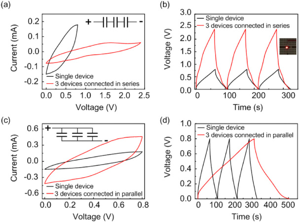
Figure 4. (a) CV with a scan rate of 100 mV s−1 and (b) galvanostatic charge and discharge curves at 19.8 μA (50 μA cm−2) of three MSCs connected in series. The inset in (a) is a schematic diagram of the circuit and (b) is the LED powered by three MSCs connected in series. (c) CV with a scan rate of 100 mV s−1 and (d) galvanostatic charge and discharge curves at 19.8 μA of three MSCs connected in parallel. The inset in (c) is a schematic diagram of the circuit. The single device performance shown in all figures is for comparison.
Download figure:
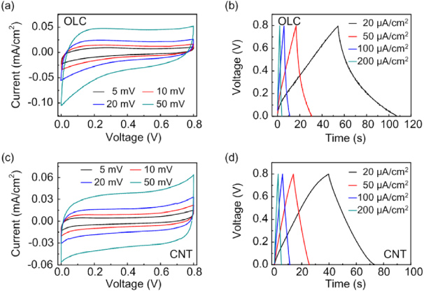
Standard image High-resolution imageIn order to demonstrate that screen printing technology is generally suitable for various active materials, OLC and CNTs have been printed into the MSCs. The performance of the OLC and CNT based MSCs with a channel length of 600 μm is shown in figure 5. As we expected, the carbonaceous MSCs show typical triangle-shaped charge/discharge curves, indicating their energy storage ability. The specific capacities of the OLC MSCs are 1.32, 0.87, 0.64 and 0.47 mF cm−2 at current densities of 20, 50, 100 and 200 μA cm−2, respectively(figure 5(b)). In contrast, the capacities of the CNT MSC are 0.84, 0.73, 0.66 and 0.60 mF cm−2 at current densities of 20, 50, 100 and 200 μA cm−2, respectively (figure 5(d)). The results indicate that not only metal oxide based pseudo-supercapacitors (MnO2/OLC), but also carbonaceous based supercapacitors can be fabricated as micro-chips on a flexible substrate using this technology. To the best of our knowledge, there have been no reports on metal oxide/carbonaceous MSCs on plastic flexible substrates due to the requirements/limitations of the fabrication technology, such as high growth temperature of the metal oxide and/or carbon materials. These results are very promising for demonstrate the possibility of using screen printing technology to integrate various active materials into MSCs onto different substrates.
Figure 5. (a) CV and (b) charge/discharge curves of the OLC MSCs with various scan rates and current densities, respectively. (c) CV and (d) charge/discharge curves of the CNT MSCs with various scan rates and current densities, respectively. All devices were fabricated on PET substrate by screen printing technology.
Download figure:
Standard image High-resolution image
From a materials perspective, screen printing technology paves the way for the integration of various active materials into MSCs which were previously incompatible using conventional device fabrication methods. In addition, negative and positive electrode active materials and even the current collector (metal electrode) can be changed by printing different materials for different layers. This flexibility gives more space to further improve the energy density and power density of the devices. Last but not least, the cost of screen printing is very low since the entire process can be done in ambient conditions or a low vacuum oven without high cost metal deposition equipment and complicated fabrication processes. However, this technique is still in its infancy, and further improvement is demanded for large scale application. The yield of high quality printed devices greatly depends on the printing conditions. For example, voids may be generated if the process is not well controlled (see the red dotted circle line in figure S7b available at stacks.iop.org/Nano/25/094010/mmedia). Therefore, attention must be paid to the synthesis and optimization of active material ink as well as the printing parameters including ink velocity, printing speed and surface treatment of the substrates. We are also working on reducing the channel length to an even smaller level to improve the performance of the printed MSCs. With both the efforts from materials synthesis and process optimization, high performance all-printed MSCs with a channel length below 100 μm can be expected [43–45].
4. Conclusions
A solid flexible MSC has been fabricated by simple screen printing technique. An all-solid flexible MSC was composed of Ag electrode, MnO2/OLC active material, PV A/H3PO4 solid electrolyte and PET plastic substrate. The printed solid flexible MSCs exhibit a high capacity of 7.04 mF cm−2, mainly originating from the contribution of the active material MnO2/OLC. In addition, the MSC can maintain more than 80% of its specific capacity after 1000 cycles. Furthermore, OLC and CNTs were also printed onto the MSCs to show that this method is a general route for obtaining high performance solid flexible MSCs.
Acknowledgment
This work is supported by SMART innovation grant and NRF proof-of-concept (POC) grant RGNRF1201.